semi合集-English.pdf - 第5464页
SEMI PR9-0705 © SEMI 2005 8 8.6.4 Fluid leak test. Visual inspectio n, pressure drop test (time to lose pressure). 8.6.5 Helium leak test (any existing standards we can refer to?) 8.6.6 Temperature cycles. Cycle parts in…

SEMI PR9-0705 © SEMI 2005 7
Silicon Polymers Glass Metals Ceramics Plastics
Organo-Metallic and
Siloxanes
5
Oxygen, Oxides and
Sulfides
5 7 7 7
Nitrogen and Nitrogen
Compounds
5 7 7 7
Acids
U 6 7 7
#1
A = Acceptable. This combination of fluid and material is acceptable or generally acceptable use when small effects of
permeation are inconsequential to use.
#2
U = Unacceptable in most applications where material and chemical interaction are significant.
#3
number = see footnote.
7.8.2 Example of How to Use This Chart and Guide
7.8.2.1 An engineering team is tasked to design a portable, matchbox-sized analytical system to detect, quantify,
and transmit data on abnormal airborne bio excursions.
8 Component Specific Guidelines
8.1 Purpose — To provide guidance on connection (methods) of discrete and integrated fluidic interconnects.”
8.2 Scope — These methods are limited to connections from microfluidic components to other microfluidic
components, and from microfluidic components to fluidic adapters.
8.3 Category — discrete and/or integrated components that provide interconnects on chip or between chips.
Examples of applications include: pressure sensor, flow sensor, temperature sensor, valves and pumps, as well as
adaptors. They can integrate with fluidic interconnect components.
8.4 Fabrication method — This section mainly discusses wafer-level interconnect fabrication methods.
8.4.1 Fusion bonding for Si wafers. Suitable for wafers that can tolerate high processing temperature
8.4.2 Anodic bonding for Si/Glass. Suitable for wafers that can tolerate high temperature and strong electrical field
8.4.3 Polymer bonding with intermediate layers such as SU-8, polyimide, PMMA, and BCB. Low temperature
bonding technique that is suitable for bioassays and post CMOS device integration with MEMS components. The
bonding chemical environment may be harmful to some biochemical chip functions and must be managed carefully.
8.4.4 Double side tape with pressurized press. Assembly method to make components, subsystems or system.
8.4.5 Thermocompression bonding. Use metal intermediate layer. Suitable for fluids containing organic solvents.
8.5 Adapters
8.5.1 End fittings (VCR
®
, Swagelok). Refer to manufacturer’s instructions. They are typically comprised of a nut
and a ferrule—have the important function of providing the physical connection of tubing throughout a chip and
between chips.
8.6 Testing and Validation
8.6.1 The following are guidelines for validation and testing of the integrity of the components
8.6.2 Standard pull test. This evaluates the bonding strength, but not sealing quality. Refer to tool manufacturer’s
manual from suppliers such as Instron, Zwick and MTS.
8.6.3 Pressurized test. Test the maximum pressure the component can survive according to the specifications of the
designed device.

SEMI PR9-0705 © SEMI 2005 8
8.6.4 Fluid leak test. Visual inspection, pressure drop test (time to lose pressure).
8.6.5 Helium leak test (any existing standards we can refer to?)
8.6.6 Temperature cycles. Cycle parts in the expected application environments that the components will be
exposed to or in an acceleration chamber with controlled temperature.
8.6.7 In case of disposable devices, only a small sample size from a product lot can be tested. Detailed test plans
can be found in subsystem guidelines.
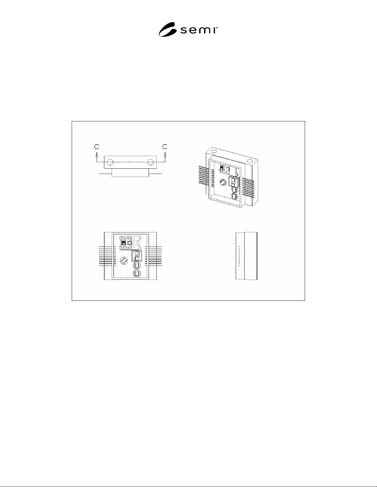
8.7 An example with a diagram is desired. See Figures 1–4.
9 Subsystem Guidelines
9.1 Purpose — Provide guidance for assembly and testing of Microfluidic subsystems, considering applicable
performance and operating specifications. Examples of performance characteristics are response time, accuracy,
reliability, drydown, and cleanliness.
9.2 Scope — These guidelines are limited to macro sealing and macro to micro sealing. It specifically excludes
wafer-scale testing. They address interconnection (fluidic, electrical, and other) of the microfluidic subsystem to the
external system. They also address interconnection of individual components within the microfluidic subsystem.
9.3 Assembly and Test Preparation
9.3.1 Visually inspect parts under microscope before assembly. Perform any testing possible at the MEMS
component level as characterization or to determine failures before integrating.
9.3.2 Assemble under hoods or in cleanroom. Wear gloves. Use electrostatic protection. Assembly should be in
the same class environment as required by user. See SEMI E129.
9.3.3 Follow manufacturer’s instructions for tightening fittings and seals and connecting parts. If applicable,
measure torque or other assembly parameters. Subsystem should have means or method to hold part being tightened
to not compromise the structural integrity of the part.
9.3.4 Seals used to connect components should be considered for thermal performance, cleanliness, and material
compatibility. See ¶9.4.?.
9.3.5 Test systems should have filters installed upstream of the device under test. Select pore size similar to pore
size used in final application.
9.4 Verification and Validation
9.4.1 The following are guidelines for verification and validation. Some may also apply to production testing.
9.4.2 Test for particles and for other contamination characteristics such as moisture dry down as required by end
user as a system. See ASTM F1394 (particle), SEMI E66 (particle), ASTM F1397 (moisture).
9.4.3 Test for applicable performance parameters such as accuracy using NIST traceable standards. Time or
process response characterizations should model system and connection volumes, based on specification designed
for. If the final application can not be duplicated, consider final system in the data analysis. For faster process time
minimize volume and surface area between the flow control system and chamber. Test in gas or liquid that it will be
used with or list substitute/test gas or liquid on test report.
9.4.4 Cycle parts in environment that they will be used in or in an accelerated mode. This is to model mean time to
failure or other parameters of reliability. At intervals test for most important performance or operating parameters.
See ASTM F1394, ASTM F1373.
9.4.5
Leak test mechanical connections using inboard leak detection method. For positive shut-off components test
for leak across the seat. Reference SEMI F1.
9.4.6 Test for performance at maximum and minimum temperatures based on product specifications.
9.4.7 Test for performance at maximum and minimum pressures (input and output) based on product specifications.
9.4.8 Test for burst and proof pressures, Reference SEMI E28.
SEMI PR9-0705 © SEMI 2005 9
9.4.9 Test for shock and vibration. Check for operation and leak integrity before and after testing. MIL-STD 810
9.4.10 Test for performance at maximum and minimum voltages based on product specifications.
9.4.11 Perform electrical testing and validation. Check for power consumption, response time, noise, dielectric
breakdown, resistance fluctuations, others?
9.4.12 Test for compatibility with typical, operating and/or specified fluids for validation testing.
9.4.12.1 See Figures 1–4 of a MEMS System with subsystem fluidic interface features.
9.4.12.2 Courtesy Redwood MicroSystems
Figure 1
Mechanical Drawing Showing MEMS System