semi合集-English.pdf - 第669页
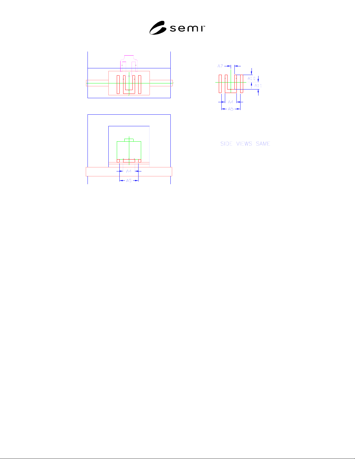
SEMI E85-0705 © SEMI 1999, 2005 23 A4 200 mm A10 130 mm A5 312 mm A11 112 mm A7 60 mm Figure 15 AMHS Interbay Loadport Opti on D’
SEMI E85-0705 © SEMI 1999, 2005 22
A4 200 mm A10 130 mm
A5 312 mm A11 112 mm
A7 60 mm
Figure 14
AMHS Interbay Loadport Option C’
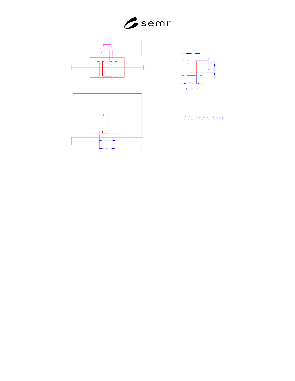
SEMI E85-0705 © SEMI 1999, 2005 23
A4 200 mm A10 130 mm
A5 312 mm A11 112 mm
A7 60 mm
Figure 15
AMHS Interbay Loadport Option D’

SEMI E85-0705 © SEMI 1999, 2005 24
RELATED INFORMATION 1
NOTICE: This related information is not an official part of SEMI E85. This related information was approved for publication by
full letter ballot procedures on July 19, 2001.
R1-1 Except for Option F and F’, the carrier may only rest on two of the three kinematic pins as defined in SEMI
E57 to allow for transfer using the secondary set of kinematic pins. The AMHS supplier must allow the rear of the
carrier to rest on a SEMI defined surface defined in SEMI E47.1 (front-opening box) or SEMI E1.9 (open cassette)
to ensure the carrier is properly supported. The AMHS supplier should also investigate the stability of the FOUP if
it rests on only two pins. One possible solution would be to add a lead-in or retaining feature that interfaces with a
SEMI defined outer carrier surface defined in SEMI E47.1 (front-opening box) or SEMI E1.9 (open cassette).
R1-2 To avoid interfering with the lead-in capability (misalignment correction) function of the kinematic couplings,
it is recommended that no part of the storage device (other than the kinematic couplings) come horizontally closer
than 10 mm (0.39 in.) to the carrier.
R1-3 It is recommended that the systems that deliver carriers to AMHS interbay load ports have a mechanism to
correct for misalignment of storage devices and load ports.
R1-4 The dimension H2 which defines the depth of the exclusion zone that allows for carrier transfer using the
secondary set of kinematic pins, might be reduced in the future.
R1-5 Dimension C5 (for Option C) and D5 (for Option D) define the range required for stocker reach. Through
teaching or adjustment the stocker must be able to transfer carriers from passive interbay transport systems which
have a centerline within this range (250 ± 50 mm). This dimension is measured from the center point of the wafers
on the interbay transport system.
R1-6 AMHS equipment can be configured with a variety of load ports chosen from the options defined in Section
7.5. Figure R1-1a shows a storage device with two Option A interbay load ports, which may work with an active
transport and any carrier.
R1-7 An IC manufacturer or user could also specify the same Option A stocker, but with only one interbay load
port. Figure R1-1b shows a storage device with two Option B interbay load ports, which may work with carriers
delivered by a passive transport or an overhead transport system. Again, an IC manufacturer or user could also
specify the same Option B stocker, but with only one interbay load port.
R1-8 For Example Only: AMHS suppliers may implement lead-in features in various methods which promote
registration using any of the SEMI defined dimensions and features of the carrier.