semi合集-English.pdf - 第5055页
SEMI M20-1104 © SEMI 1991, 2004 4 RELATED INFORMATION 1 APPLICATIONS OF THE WA FER COORDINATE SYSTEM NOTICE: This related infor mation is not an official par t of SEMI M20. It was de veloped during the origi nal developm…
SEMI M20-1104 © SEMI 1991, 2004 3
x
y
(x
1
, y
1
)
(R
1
,
1
)
1
x
y
(x
1
, y
1
)
(R
1
,
1
)
1
x
y
(x
1
, y
1
)
(R
1
,
1
)
1
NOTE: The primary fiducial may be a flat or a notch.
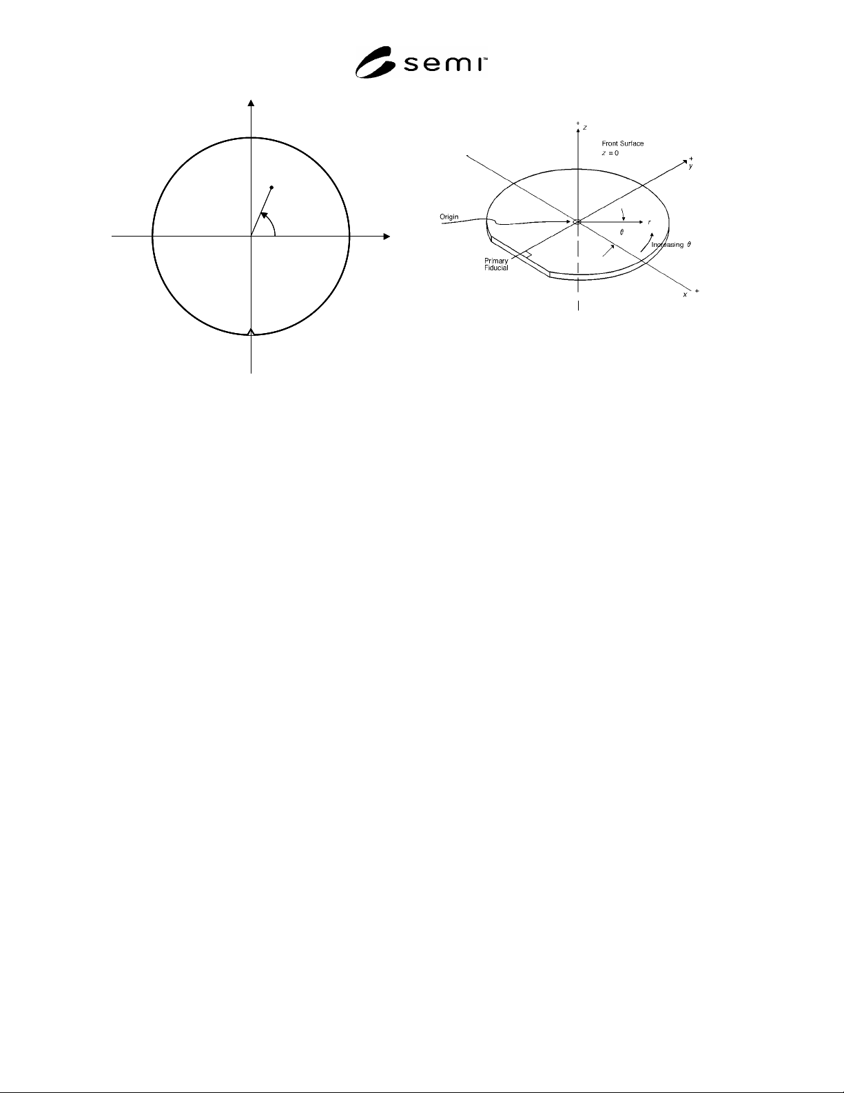
Figure 1
Front Surface Coordinate System
7.2.2 With the primary fiducial in the negative y
direction (downward or toward the operator), the
positive x-axis points toward the left. In this way the x-
y-coordinates of a point on the back surface are the
same as the x-y coordinates of the point directly through
the wafer on the front surface.
7.3 Three-dimensional Coordinates
7.3.1 Place the wafer with the front surface up.
7.3.2 Erect the z-axis through the center of the wafer
surface and perpendicular to the plane of the surface
with the positive direction above the front surface (see
Figure 2).
7.3.3 Assign the zero point of the z-axis in accordance
with the application.
7.3.3.1 For example, for geometric measurements,
such as warp, the center of the z-axis may be at the
geometrical center of the wafer in three dimensions.
7.3.3.2 For front surface flatness measurements, the
zero point of the z-axis is usually taken at the reference
plane, which is chosen in accordance with the particular
flatness parameter being determined.
7.3.3.3 Other applications may require locating the
center of the z-axis at a different position.
7.3.3.4 For thickness or thickness variation
measurements, the zero point of the z-axis may be taken
at the center of the back surface of the wafer.
NOTE: The primary fiducial may be a flat or a notch.
Figure 2
Wafer Coordinate System with z-axis Direction
Indicated

SEMI M20-1104 © SEMI 1991, 2004 4
RELATED INFORMATION 1
APPLICATIONS OF THE WAFER COORDINATE SYSTEM
NOTICE: This related information is not an official part of SEMI M20. It was developed during the original
development of the document. This related information was approved for publication by full letter ballot
procedures.
R1-1 SEMI E5, in Stream 12 — Wafer Mapping, delineates how a coordinate system for reporting position data
may be communicated. The origin of this coordinate system, which is specified by the equipment when generating
the wafer map, may be the site at any of the four corners of the array or at the array center. In addition, the stream
provides for transmission of an arbitrary number of reference points to relate the map coordinate system to the
physical wafer. The wafer coordinate system may be used to establish the locations of these reference points and of
the origin of the map coordinate system.
R1-2 SEMI M17 defines a polar array of 1000 elements which can be used to identify the locations on a wafer of
extended defects such as slip. This array is consistent with the wafer coordinate system.
NOTICE: SEMI makes no warranties or representations as to the suitability of the standards set forth herein for any
particular application. The determination of the suitability of the standard is solely the responsibility of the user.
Users are cautioned to refer to manufacturer’s instructions, product labels, product data sheets, and other relevant
literature respecting any materials mentioned herein. These standards are subject to change without notice.
The user’s attention is called to the possibility that compliance with this standard may require use of copyrighted
material or of an invention covered by patent rights. By publication of this standard, SEMI takes no position
respecting the validity of any patent rights or copyrights asserted in connection with any item mentioned in this
standard. Users of this standard are expressly advised that determination of any such patent rights or copyrights, and
the risk of infringement of such rights, are entirely their own responsibility.
Copyright by SEMI® (Semiconductor Equipment and Materials
International), 3081 Zanker Road, San Jose, CA 95134. Reproduction
of the contents in whole or in part is forbidden without express written
consent of SEMI.
SEMI M21-0304 © SEMI 1992, 2004 1
SEMI M21-0304
GUIDE FOR ASSIGNING ADDRESSES TO RECTANGULAR ELEMENTS
IN A CARTESIAN ARRAY
This guide was technically approved by the Global Silicon Wafer Committee and is the direct responsibility
of the North American Silicon Wafer Committee. Current edition approved by the North American Regional
Standards Committee on October 16, 2003. Initially available at www.semi.org February 2004; to be
published March 2004. Originally published in 1992; last published September 1998.
1 Purpose
1.1 It is frequently very useful to have a standardized
method for labeling elements in an array on a silicon
wafer surface.
1.2 This guide defines an element addressing conven-
tion for locating and uniquely identifying rectangular
elements in a Cartesian array.
1.3 Such arrays are useful in locating sites for site
flatness characterization, defect mapping, determination
of parametric distributions, etc. on unpatterned
semiconductor wafers.
2 Scope
2.1 This guide covers procedures for assigning
addresses that can be used to locate and identify
rectangular elements in a Cartesian array. The array
may be regular or tiled in one direction.
2.2 Relating the position of the array to the wafer
surface is outside the scope of this guide, but it may be
established through use of the wafer coordinate system
defined in SEMI M20.
2.3 This guide covers procedures for assigning a
unique identification (address) for each element in the
array. An example of the results obtained by following
this procedure are given in Related Information 1.
2.4 The element addressing convention in this guide
provides an orderly progression along perpendicular
directions with addresses of adjacent elements in any
direction differing by 1. Consequently, distances may
be calculated in a unified way.
2.5 For complex patterns, more than one array on a
wafer may be defined and related to the same
coordinate axes.
2.6 The element addressing convention in this guide is
consistent with that of the polar array specified in SEMI
M17. In addition, element addresses can be readily
transformed to addresses in other types of addressing
conventions for Cartesian arrays as described in Related
Information 2.
NOTICE: This standard does not purport to address
safety issues, if any, associated with its use. It is the
responsibility of the users of this standard to establish
appropriate safety and health practices and determine
the applicability of regulatory or other limitations prior
to use.
3 Referenced Standards
3.1 SEMI Standards
SEMI M1 — Specifications for Polished
Monocrystalline Silicon Wafers
SEMI M2 — Specification for Silicon Epitaxial Wafers
SEMI M11 — Specification for Silicon Epitaxial
Wafers for Advanced Applications
SEMI M17 — Guide for a Universal Wafer Grid
SEMI M20 — Practice for Establishing a Wafer
Coordinate System
SEMI MF1241 — Terminology of Silicon Technology
NOTICE: Unless otherwise indicated, all documents
cited shall be the latest published versions.
4 Terminology
4.1 Many terms used in silicon wafer technology are
defined in SEMI MF1241.
4.2 Definitions of additional terms may be found in
SEMI M1, SEMI M2, or SEMI M11.
5 Array Element Layout
5.1 The array is constructed from m vertical columns
and n horizontal rows of identical elements of
dimension a horizontally and b vertically. The number
of elements in different rows and columns may vary to
suit the application.
5.2 The address of an element is given by two numbers
separated by a comma: (i,j). The first number, i,
indicates the column and the second, j, the row.
5.3 The longest row and the longest column are used in
identifying the Starting Element, which is assigned the
address (0,0).