semi合集-English.pdf - 第7179页
SEMI S23-0705 © SEMI 2005 12 removed per y ear by cooli ng water in a sim ilar manner, using the “Re moval via Water” conversio n factor. Finall y subtract the last two energy values fro m the first to get the heat load …

SEMI S23-0705 © SEMI 2005 11
R1-2.2 Estimated Hours per Year
R1-2.2.1 It is recommended that the hours per year the equipment spends processing and idling be estimated as
6,132 and 2,190 respectively. This assumes 8,760 hours per year of opportunity. And, it assumes the equipment will
be shut down (i.e. not consuming) for 5% of the 8,760 hours. To provide reporting commonality within the
semiconductor industry, it is strongly recommended that alternate values not be used.
NOTE 1: The number of hours per year a piece of equipment spends processing or idling are not solely related to the
equipment’s “availability” (described in SEMI E10). The number also depends on the processing demands of the end user, which
may be less than the equipment’s availability.
R1-2.3 Conversion Factor Basis
R1-2.3.1 A key basis for some conversion factors is the condition(s) under which the conversion factor was
developed. For example, the conversion factor for water supplied at 25C might be different from the conversion
factor for water supplied at room temperature because in addition to the energy used to distribute the water, energy
is used to refrigerate the water.
R1-2.3.2 Table 2 of the guide includes some of the basis conditions for the recommended conversion factors.
Where the actual conditions of the utility or material supply are different from these basis conditions, the conversion
factor is less valid. There is no recommended method for adjusting the factor in response to these differences in all
cases.
R1-2.4 Alternate Conversion Factors
R1-2.4.1 An equipment end user may have developed a set of conversion factors that they prefer for their business
model. It is recommended that these also be considered.
R1-2.4.2 An alternate set of conversion factors for different equipment use regions may be useful for analyzing the
impact of differing utility and material production efficiencies in those regions.
R1-2.4.3 A spreadsheet program can be used to show several different sets of conversion factors and the related
conversion outcomes for a given set of utility and materials use rate data.
R1-2.4.4 The development of meaningful conversion factors requires a certain amount of data gathering and
analysis. It is recommended that if alternate conversion factors are used, the supporting data and analysis be
prepared and made available to interested parties for review.
R1-2.5 Process Chemical Conversion Factors
R1-2.5.1 It is likely that any process chemical conversion factor (i.e. the energy consumed to produce one cubic
meter process chemical) is much greater than any other conversion factor listed in Table 3.
R1-2.5.2 A very rough analysis based on data from other industries, indicates, for example, that simple chemicals
such as K20 or ethanol have energy equivalents much greater than 1000 kWh/m3.
R1-2.6 Heat Load Calculation
R1-2.6.1 The provided heat load calculation is based on the idea that all electrical energy supplied to the equipment
becomes heat input which is transferred by one of three heat transfer modes.
R1-2.6.2 If there are other sources of heat within the equipment, such as chemical reactions, that are significant,
they should also be considered part of the heat input.
R1-2.6.3 The heat energy is typically transferred by radiation and convection into the environment surrounding the
equipment and remaining heat energy is transferred by convection to the process exhaust and conduction to the
process cooling water. Theoretically all three heat transfer modes may be involved in for all heat transfer practices
(tool to room, tool to exhaust, and tool to cooling water).
R1-2.6.4 The heat removed by the air and water is determined through calculations involving particular constants
(i.e. specific heat and specific gravity).
R1-2.6.5 The heat load calculation is taken in four steps. First estimate the electrical energy delivered to the
equipment per year. Next estimate the energy removed per year by exhausted air using the volume of air removed,
the input-output air temperature difference, and the “Removal via Air” conversion factor. Then estimate the energy
SEMI S23-0705 © SEMI 2005 12
removed per year by cooling water in a similar manner, using the “Removal via Water” conversion factor. Finally
subtract the last two energy values from the first to get the heat load of the equipment that is transferred to the room
in which the equipment resides.
R1-2.6.6 Once the room heat load of the equipment has been estimated, the “Heat Load Burden” conversion factor
can be used to express the energy required to remove that heat from the equipment environment.
R1-2.7 Electrical Energy
R1-2.7.1 A conversion factor of 1 is presented for electrical energy. The value thus calculated is the electrical
energy supplied to the equipment.
R1-2.7.2 The amount of energy required to generate the electricity is not addressed by this conversion factor of 1.
This additional detail may be useful, but the applicable conversion factor will depend on the technologies used to
generate and distribute the electricity that is used.
NOTE 2: For example, the energy content of coal is approximately 8000 kWh per ton. If the electricity provider must burn one
ton of coal to generate 6000 kWh of electrical energy, the electrical energy conversion factor could be set to 1.33 (no units) to
express the actual energy required to produce 1 kWh of electrical energy.
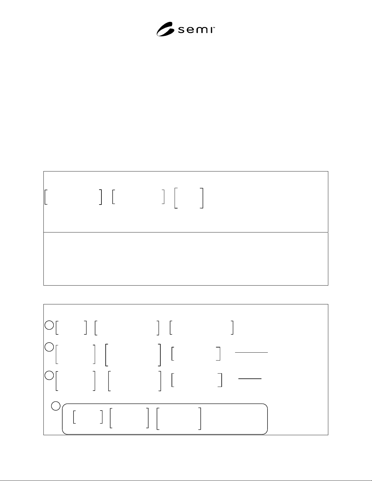
Table R1-2 Energy Conversion Calculation Model and Example
Calculation Model
Use-rate Measurement
(processing or idling)
×
Hours per Year
(processing or idling)
Energy
Conversion
Facto
r
×
=
Estimated Energy
Consumed
per Year
Estimated Hours per Year: Processing = 6132; Idling = 2190
Example Calculation (processing)
Cooling Water (20-25C) for recipe “X”
Use rate measured during processing: 0.500 gal/min = 0.114 m
3
/hr
Annual amount used for processing: 0.114 m
3
/hr x 6,132 hr = 698 m
3
Estimated annual energy equivalent: 698 m
3
x 1.78 kWh/m
3
= 124x10
1
kWh
Table R1-3 Heat Load Calculation Model and Example
Calculation Model
Heat Removal
per Year
ai
r
Volume of air
exhausted from
equipment per year
Heat Removal
per Year
water
Volume of water
exhausted from
equipment per year
Heat Removal
per Year
air
Heat Removal
per Year
water
Heat Input
per Year
–
+
–
=
Estimated Heat
Burden per Year
Heat Input
per Year
=
E
lectrical energy input to
equipment per year
Other Heat Sources
(e.g. chemical reactions)
×
=
(Inlet air temp) –
(Outlet air temp)
×
3.24x10
-4
kWh
m
3
°C
×
=
(Inlet water temp) –
(Outlet water temp)
×
1.16 kWh
m
3
°C
1
2
3
4
Removal via Air Conv. Factor
Removal via Water Conv. Factor

SEMI S23-0705 © SEMI 2005 13
Example Calculation (idling) for Recipe “X”
Electricity
Mean real power = 4.16E + 1 kW
Heat Input per Year = 4.16E + 1 kW × 2190 hr = 9.11E + 4 kWh (no other heat input sources)
Air Exhaust
Specified source temperature = 18°C Measured average output temperature = 23°C
Mean temperature difference = 5°C Measured exhaust rate = 50 cfm (5.1E + 3 m
3
/hr)
Volume used per year = 5.1E + 3 m
3
/hr × 2190 hr = 1.12E + 7 m
3
Heat Removal per year = (5°C × 1.12E + 7 m
3
× 3.24E 4 kWh/(m
3
°C) = 1.81E + 4 kWh
Cooling Water
Specified ambient temperature = 20°C Measured average output temperature = 22°C
Mean temperature difference = 2°C Measured flow rate = 1 L/m (0.06 m
3
/hr)
Volume used per year = 0.06 m
3
/hr × 2190 hr = 1E + 2 m
3
Heat Removal per year = (2°C × 1E + 2 m
3
× 1.16 kWh/(m
3
°C) = 2E + 2 kWh
Room Heat Burden
9.11E + 4 kWh – 1.81E + 4 kWh – 2E + 2 kWh = 7.28E + 4 kWh
NOTICE: SEMI makes no warranties or representations as to the suitability of the standards set forth herein for any
particular application. The determination of the suitability of the standard is solely the responsibility of the user.
Users are cautioned to refer to manufacturer's instructions, product labels, product data sheets, and other relevant
literature, respecting any materials or equipment mentioned herein. These standards are subject to change without
notice.
By publication of this standard, Semiconductor Equipment and Materials International (SEMI) takes no position
respecting the validity of any patent rights or copyrights asserted in connection with any items mentioned in this
standard. Users of this standard are expressly advised that determination of any such patent rights or copyrights, and
the risk of infringement of such rights are entirely their own responsibility.
Copyright by SEMI® (Semiconductor Equipment and Materials
International), 3081 Zanker Road, San Jose, CA 95134. Reproduction of
the contents in whole or in part is forbidden without express written
consent of SEMI.