semi合集-English.pdf - 第213页
SEMI E28-92 © SEMI 1992, 2004 1 SEMI E28-92 (Reapproved 1104) GUIDELINE FOR PRESSURE SPECIF ICATIONS OF THE MASS FLOW CONTROLLER This guideline was technically reapproved by the Globa l Gases Committee and is the direct …
SEMI E27-92 © SEMI 1992, 2004 2
meters this is full scale or the highest actual flow value
at which the instrument is specified.
6 Significance and Use
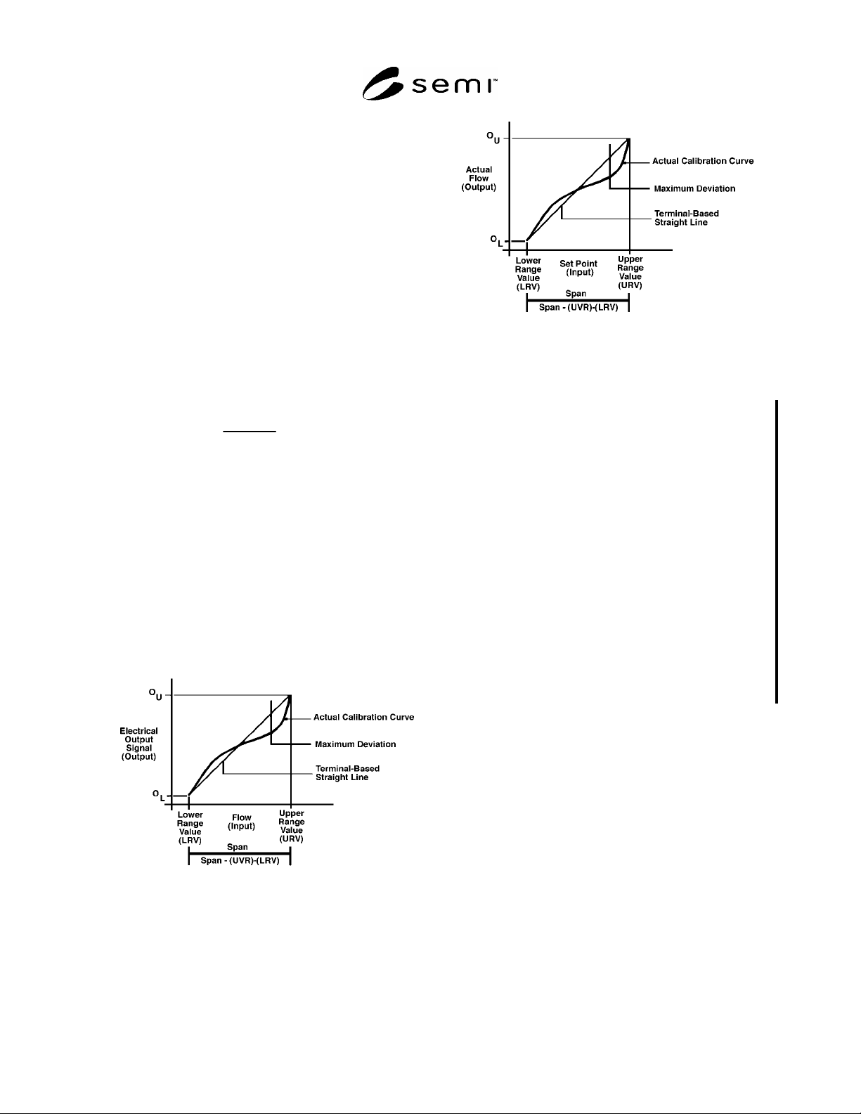
6.1 The linearity of a mass flow controller (MFC) is
expressed in terms of its actual flow output as a
function of the setpoint input (control voltage) (see
Figure 2).
6.2 The linearity of a mass flow meter (MFM) is
expressed in terms of its electrical output as a function
of the actual flow (input) through the device (see Figure
1).
6.3 Terminal-based linearity shall be used to describe
the linearity of MFCs and MFMs. The maximum
deviation is expressed as a percentage of the algebraic
difference between the output at the upper range value
and the output at the lower range value.
Linearity =
d
MAX
O
U
O
L
100
where O
U
= output at the upper range value
O
L
= output at the lower range value
d
MAX
= maximum deviation
6.3.1 Terminal-based linearity may be expressed as a
percentage of some other value (such as a percentage of
reading) if it is so identified.
6.3.2 If results are reported using range values other
than zero and full scale, the actual range values used in
the calculation shall be reported.
Figure 1
Terminal-Based Linearity for Mass Flow Meter
Figure 2
Terminal-Based Linearity for Mass Flow Controller
NOTICE: SEMI makes no warranties or
representations as to the suitability of the standards set
forth herein for any particular application. The
determination of the suitability of the standard is solely
the responsibility of the user. Users are cautioned to
refer to manufacturer's instructions, product labels,
product data sheets, and other relevant literature,
respecting any materials or equipment mentioned
herein. These standards are subject to change without
notice.
By publication of this standard, Semiconductor
Equipment and Materials International (SEMI) takes no
position respecting the validity of any patent rights or
copyrights asserted in connection with any items
mentioned in this standard. Users of this standard are
expressly advised that determination of any such patent
rights or copyrights, and the risk of infringement of
such rights are entirely their own responsibility.
Copyright by SEMI® (Semiconductor Equipment and Materials
International), 3081 Zanker Road, San Jose, CA 95134. Reproduction of
the contents in whole or in part is forbidden without express written
consent of SEMI.
SEMI E28-92 © SEMI 1992, 2004 1
SEMI E28-92 (Reapproved 1104)
GUIDELINE FOR PRESSURE SPECIFICATIONS OF THE MASS FLOW
CONTROLLER
This guideline was technically reapproved by the Global Gases Committee and is the direct responsibility of
the North American Gases Committee. Current edition approved by the North American Regional Standards
Committee in July 11, 2004. Initially available at www.semi.org September 2004; to be published November
2004. Originally published in 1992; last published February 1999.
1 Purpose
1.1 The purpose of this guideline is to establish a
uniform, worldwide means to describe pressure
parameters as they relate to mass flow controllers. It is
intended to prevent confusion and misunderstanding
between manufacturers and users.
2 Scope
2.1 This guideline contains definitions of terms which
describe gas pressure in mass flow controllers as used
in the semiconductor industry. SI units are the
reference units for this document.
NOTICE: This standard does not purport to address
safety issues, if any, associated with its use. It is the
responsibility of the users of this standard to establish
appropriate safety and health practices and determine
the applicability of regulatory or other limitations prior
to use.
3 Referenced Standards
3.1 SEMI Standard
SEMI E12 — Standard for Standard Pressure and
Standard Temperature for Flow Units Used in Mass
Flow Meters and Mass Flow Controllers
NOTICE: Unless otherwise indicated, all documents
cited shall be the latest published versions.
4 Terminology
4.1 Definitions
4.1.1 units of pressure — several units of pressure are
commonly used in conjunction with MFCs. The Pascal
is the preferred unit of pressure for use within the
semiconductor industry. Units of pressure include the
following:
Pascal (Pa)
Pounds per square inch (psi)
Torr (T)
Kilograms per square centimeter (kg/cm
2
)
Bar (B)
NOTE 1: Units of pressure are sometimes expressed as an
equivalent height of a column of some liquid, such as
millimeters of mercury or inches of water. These units
require correction to some standard for liquid density and
gravity. As these corrections are neither broadly standardized
nor often even addressed, their use should be avoided.
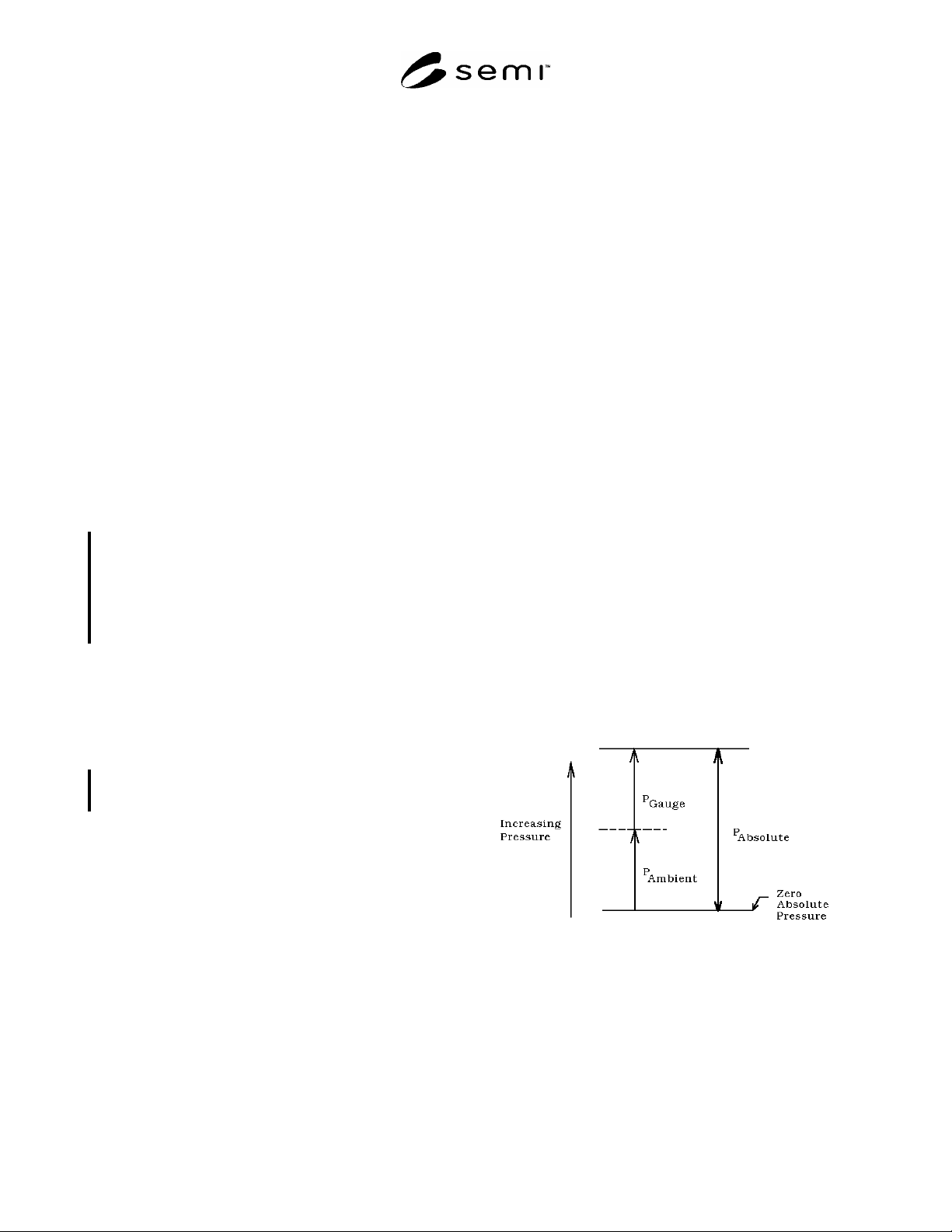
4.1.2 absolute pressure — the pressure measured
relative to zero pressure (perfect vacuum) (see Figure
1).
NOTE 2: Absolute pressure is the pressure illustrated by the
ideal gas law, PV = nRT. For example, when the number of
moles, n, equals zero (no molecules), absolute pressure, P,
equals zero. To indicate unambiguously that a pressure
measurement is absolute, the following abbreviations should
be used:
Pa — Pascal (absolute assumed)
psi (a) — Pounds per square inch, absolute
Torr — Torr (absolute assumed)
kg/cm
2
(a) — Kilograms per square centimeter, absolute
B (a) — Bar, absolute
4.1.2.1 Units such as Pascal and Torr are customarily
absolute units.
Figure 1
Relationship Between Absolute, Gauge,
and Ambient Pressure
SEMI E28-92 © SEMI 1992, 2004 2
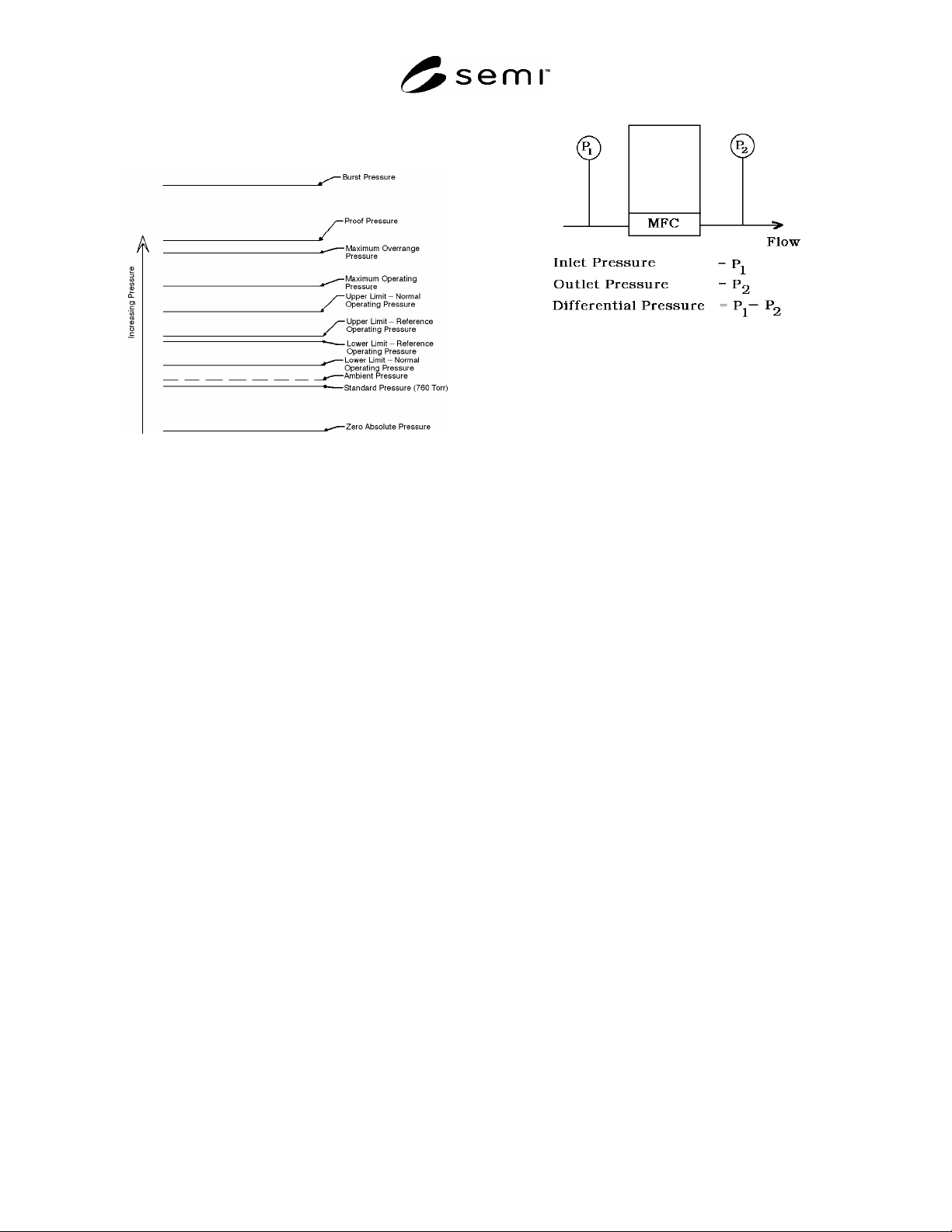
4.1.3 ambient pressure — the absolute pressure of the
medium surrounding the MFC (see Figure 2).
Figure 2
Pressure Definitions for MFCs
4.1.4 burst pressure — the gas pressure at which the
MFC may rupture.
4.1.5 differential pressure — the difference in absolute
pressure between two points of measurement in a
system (see Figure 3).
NOTE 3: To indicate unambiguously that a pressure
measurement is differential, the following abbreviations
should be used:
Pa (d) — Pascal, differential
psi (d) — Pounds per square inch, differential
Torr (d) — Torr, differential
kg/cm
2
(d) — Kilograms per square centimeter,
differential
B (d) — Bar, differential
4.1.5.1 Gauge pressures may also be used in the
differential pressure calculation if consistency is
maintained. A common error would be to take the
difference between an inlet gauge pressure and an outlet
absolute pressure without first converting to common
units.
4.1.5.2 As it applies to an MFC, differential pressure is
usually the measured difference in pressures between
the gas inlet and outlet fittings of the MFC.
Figure 3
Definition of Differential Pressure for MFCs
4.1.6 gauge pressure — the differential pressure
measured relative to ambient pressure. For example,
when the pressure within a system equals the prevailing
ambient pressure, the gauge pressure equals zero (see
Figure 1).
NOTE 4: To indicate unambiguously that a pressure
measurement is gauge, the following abbreviations should be
used:
Pa (g) — Pascal, gauge
psi (g) — Pounds per square inch, gauge
Torr (g) — Torr, gauge
kg/cm
2
— Kilograms per square centimeter, gauge
B (g) — Bar, gauge
NOTE 5: The performance of MFCs can vary significantly
with gas density. Atmospheric pressure varies with the
weather and altitude at various geographical locations. Gauge
pressure units commonly reference atmospheric pressure.
Therefore, the same gauge pressures measured at different
geographical locations may correspond to different gas
densities. For this reason, the use of gauge pressure units
with MFCs can be imprecise and should be avoided.
4.1.7 inlet pressure — the pressure at the inlet fitting
of the MFC (see Figure 3).
4.1.8 maximum operating pressure — operation is
permitted up to this inlet pressure, but performance is
not specified above normal operating pressure (see
Figure 2).
4.1.9 maximum overrange pressure — the maximum
gas pressure to which the MFC may be subjected
without degrading specified performance. When
returned to normal operating pressure, the MFC must
require no adjustment to return to specified
performance (see Figure 2).