semi合集-English.pdf - 第1334页
SEMI E30-1103 © SEMI 1992, 2003 8 events based on whether th ey can be detected and whether they are of interest. In this document, the term event has been more narrowly defined as a detectable occurrence that is signifi…
SEMI E30-1103 © SEMI 1992, 2003
7
Equipment manufacturers must document the
operation-al behavior of their equipment using state
model meth-odology. State models are discussed in
Sections 3.1 and A.5 and in a referenced article.
Documentation of a state model shall include the
following three elements:
— A state diagram showing the possible states of the
system or components of a system and all of the
possible transitions from one state to another. The
states and transitions must each be labeled. Use of
the Harel notation (see A.5) is recommended.
— A transition table listing each transition, the
beginning and end states, what stimulus triggers
the transition, and any actions taken as a result of
the transition.
— A definition of each state specifying system
behavior when that state is active.
Examples of the above elements are provided in
Section A.5.
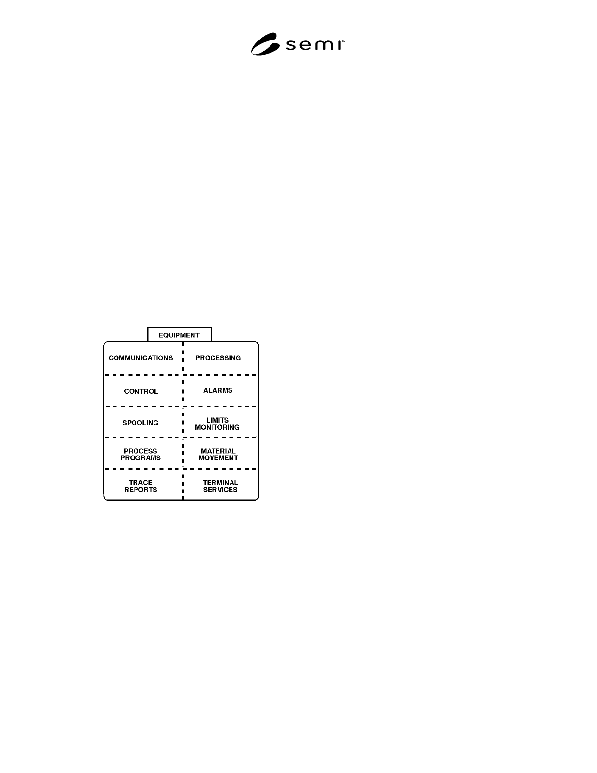
Figure 3.0
Example Equipment Component Overview
The benefits of providing state models are:
1. State machine models are a useful specification
tool,
2. A host system can anticipate machine behavior
based upon the state model,
3. End-users and equipment programmers have a
common description of machine behavior from
which to work,
4. “Legal” operations can be defined pertaining to
any machine state,
5. External event notifications can be related to
internal state transitions,
6. External commands can be related to state
transitions,
7. State model components describing different
aspects of machine control can be related to one
another (example: processing state model with
material transport state model; processing state
model with internal machine safety systems).
3.1 State Model Methodology — To document the
expected functionality of the various capabilities
described in this document, the “Statechart” notation
developed by David Harel has been adopted. An article
by Harel is listed in Section 1.5 and should be
considered “must” reading for a full understanding of
the notation. The convention used in this and following
sections is to describe the dynamic functionality of a
capability with three items: a textual description of each
state or substate defined, a table that describes the
possible transitions from one state to another, and a
graphical figure that uses the symbols defined by Harel
to illustrate the relationships of the states and
transitions. The combination of these items define the
state model for a system or component. A summary of
the Harel notation and a more detailed description of
the text, table, and figure used to define behavior with
this methodology is contained in the Application Note
A.5.
The basic unit of a state model is the state. A state is a
static set of conditions. If the conditions are met, the
state is current. These conditions might involve sensor
readings, switch positions, time of day, etc. Also part of
a state definition is a description of reactions to specific
stimuli (e.g., if message Sx,Fy is received, generate
reply message Sx,Fy + 1). Stimuli may be quite varied
but for semiconductor equipment would include
received SECS messages, expired timers, operator input
at an equipment terminal, and changes in sensor
readings.
To help clarify the interpretation of this document and
the state models described herein, it is useful to distin-
guish between a state and an event and the relationship
of one to the other. An event is dynamic rather than
static. It represents a change in conditions, or more
specifically, the awareness of such a change. An event
might involve a sensor reading exceeding a limit, a
switch changing position, or a time limit exceeded.
A change to a new active state (state transition) must
always be prompted by a change in conditions, and thus
an event. In addition, a state transition may itself be
termed an event. In fact, there are many events that may
occur on an equipment, so it is important to classify

SEMI E30-1103 © SEMI 1992, 2003
8
events based on whether they can be detected and
whether they are of interest. In this document, the term
event has been more narrowly defined as a detectable
occurrence that is significant to the equipment.
A further narrowing of the definition of event is repre-
sented by the term “collection event,” which is an event
(or group of related events) on the equipment that is
considered significant to the host. It is these events that
(if enabled) are reported to the host. By this definition,
the list of collection events for an equipment would typ-
ically be only a subset of total events. The state models
in this document are intended to be limited to the level
of detail in which the host is interested. Thus, all state
transitions defined in this standard, unless otherwise
specified, shall correspond to collection events.
3.2 Communications State Model — The
Communications State Model defines the behavior of
the equipment in relation to the existence or absence of
a communications link with the host. Section 4.1
expands on this section by defining the Establish
Communications capability. This model pertains to a
logical
connection between equipment and host rather
than a physical
connection.
3.2.1 Terminology — The terms communication fail-
ure, connection transaction failure, and communication
link are defined for use within this document only and
should not be confused with the same or similar terms
used elsewhere.
• See SEMI E4 (SECS-I) or SEMI E37 (HSMS) for
a protocol specific definitions of communications
failure.
• A connection transaction failure
occurs when
attempting to establish communications and is
caused by
— a communication failure,
— the failure to receive an S1,F14 reply within a
reply timeout limit, or
— receipt of S1,F14 that has been improperly
formatted or with COMMACK
2
not set to 0.
• A reply timeout period begins after the successful
transmission of a complete primary message for
which a reply is expected. (See SEMI E4 (SECS-I)
or SEMI E37 (HSMS) for a protocol-specific
definition of reply timeout.)
2 Establish Communications Acknowledge Code, defined in Section
4.1. See the SEMI E5 Standard for further definition of this Data
Item.
• A communication link
is established following the
first successful completion of any one S1,F13/F14
transaction with an acknowledgement of “accept”.
The establishment of this link is logical rather than
physical.
• Implementations may have mechanisms which
allow outgoing messages to be stored temporarily
prior to being sent. The noun queue
is used to
cover such stored messages. They are queued
when
placed within the queue and are dequeued
by
removing them from this storage.
• Send
includes “queue to send” or “begin the
process of attempting to send” a message. It does
not imply the successful completion of sending a
message.
• The host may attempt to establish communications
with equipment at any time due to the initialization
of the host or by independent detection of a
communications failure by the host. Thus, the host
may initiate an S1,F13/F14 transaction at any time.
3.2.2 CommDelay Timer — The CommDelay timer
represents an internal timer used to measure the interval
between attempts to send S1,F13. The length of this
interval is equal to the value in the EstablishCommuni-
cationsTimeout. The CommDelay timer is not directly
visible to the host.
EstablishCommunicationsTimeout
is the user-configur-
able equipment constant that defines the delay, in
seconds, between attempts to send S1,F13. This value
is used to initialize the CommDelay timer.
The CommDelay timer is initialized
to begin timing.
The CommDelay timer is initialized only when the state
WAIT DELAY is entered.
The CommDelay timer is expired
when it “times out,”
and the time remaining in the interval between attempts
to send is zero. When the timer expires during the state
WAIT DELAY, it triggers a new attempt to send
S1,F13 and the transition to the state WAIT CRA
3
.
3.2.3 Conventions
• The attempt to send S1,F13 is made only upon
transit into the state WAIT CRA. The CommDelay
Timer should be set to “expired” at this time.
• The CommDelay timer is initialized only upon
transit into the state WAIT DELAY. A next
3 CRA is the mnemonic defined for Establish Communications
Request Acknowledge (S1,F14).
SEMI E30-1103 © SEMI 1992, 2003
9
attempt to send S1,F13 shall occur only upon a
transit to the state WAIT CRA.
3.2.4 Communication States — There are two major
states of SECS communication, DISABLED and
ENABLED. The system default state must be user-
configurable at the equipment (e.g., via a jumper setting
or non-volatile memory variable).
Once system initialization has been achieved, the
opera-tor shall be able to change the communication
state selection at any time via equipment terminal
functions or momentary switch. A two-position type
switch must not be used due to possible conflict with
the system default.
The ENABLED state has two substates, NOT COM-
MUNICATING and COMMUNICATING, described
below. The equipment must inform the operator of the
current communication state via continuous display at
the equipment, including the NOT COMMUNI-
CATING and COMMUNICATING sub-states.
In the event of a connection transaction failure, a user-
configurable equipment constant EstablishCommunica-
tionsTimeout is used to establish the interval between
attempts to send an S1,F13 (Establish Communications
Request) while in the NOT COMMUNICATING sub-
state.
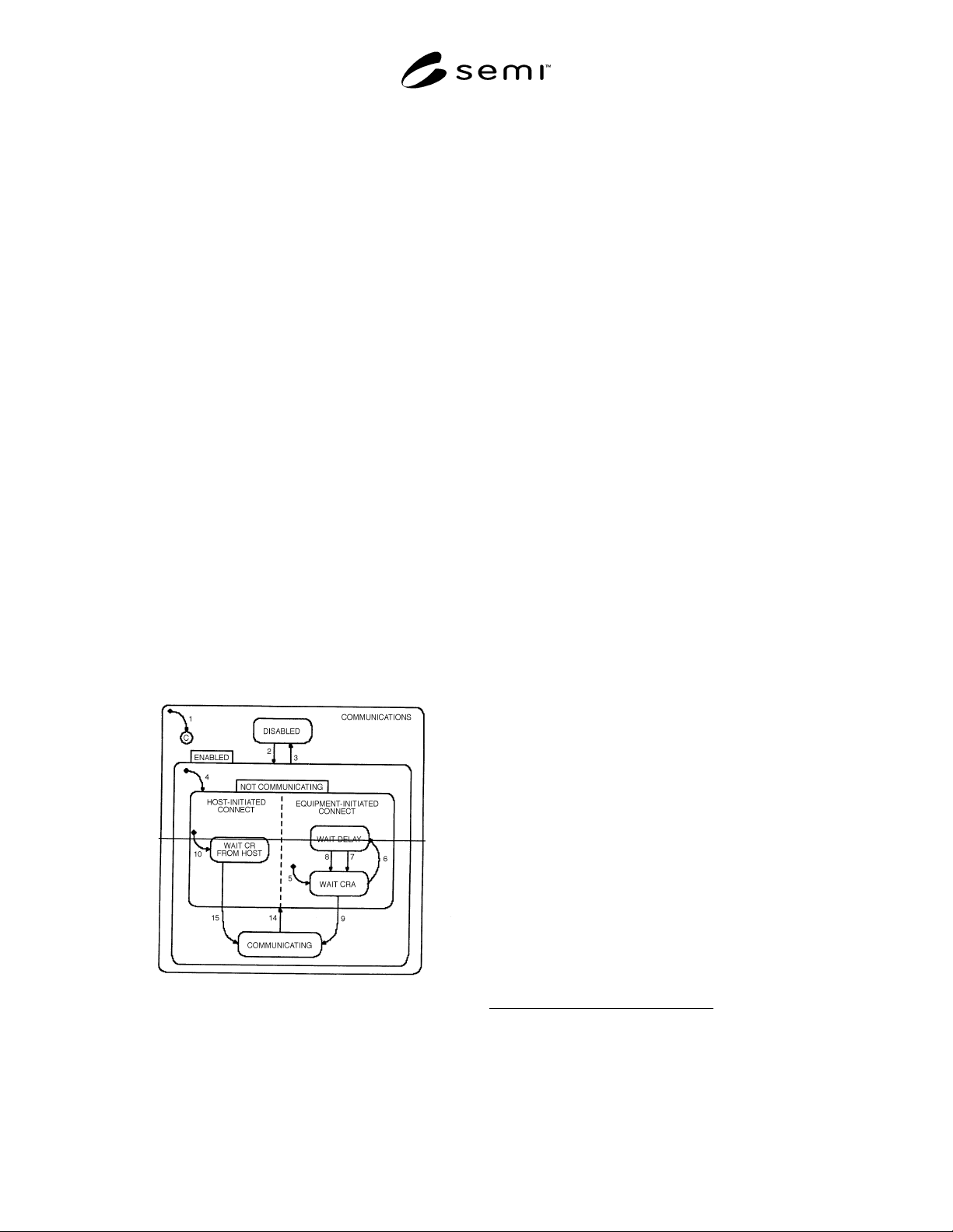
Figure 3.2.1 shows the relationship between the
superstates and substates of the Communications State
Model. A description of the events triggering state
transitions and the actions taken is given in Table 3.2.
Figure 3.2.1
Communications State Diagram
The states of the Communications State Model are
defined as follows:
DISABLED
In this state SECS-II communication with a host
computer is non-existent. If the operator switches
from ENABLED to DISABLED, all SECS-II
communications must cease immediately. Any
messages queued to send shall be discarded, and all
further action on any open transactions and
conversations shall be terminated.
4
Handling of
messages currently being transmitted is an issue for
lower level message transfer protocols and is not
addressed in this standard.
The DISABLED state is a possible system default.
ENABLED
ENABLED has two substates, COMMUNICA-
TING and NOT COMMUNICATING. Whenever
communications are enabled, either during system
initialization or through operator selection, the
substate of NOT COMMUNICATING is active
until communications are formally established.
Lower-level protocols (such as SECS-I) are
assumed to be functioning normally in that they are
capable of supporting the communication of SECS-
II syntax.
The ENABLED state is a possible system default.
ENABLED/NOT COMMUNICATING
No messages other than S1,F13, S1,F14, and S9,Fx
shall be sent while this substate is active. The
equipment shall discard any messages received
from the host other than S1,F13 or S1,F14
(Establish Communications Acknowledge). It shall
also periodically attempt to establish
communication with a host computer by issuing an
S1,F13 until communications are successfully
established. However, only one equipment-initiated
S1,F13 transaction may be open at any time.
The NOT COMMUNICATING state has two AND
substates, HOST-INITIATED CONNECT and
EQUIPMENT-INITIATED CONNECT, both of
which are active whenever the equipment is NOT
COMMUNICATING. These two substates clarify
the behavior of the equipment in the event that
both the equipment and the host attempt to
establish communications during the same period
of time
5
.
4 Refer to SEMI E5, Section 5, for definitions of SECS-II transaction
and conversation protocols.
5 Note that in the Harel notation, an exit from any AND substate is an
exit from the parent state and thus from all other AND substates of
that parent substate.