semi合集-English.pdf - 第6041页
SEMI G4-0302 © SEMI 1982, 2002 5 Table 12 Width Thick n ess Crossbow Limit from 15 mm to 24 mm 0.1 mm to under 0.3 mm 0.10 mm 0.3 mm to under 1.0 mm 0.15 mm 1.0 mm to 2.0 m m 0.20 m m over 24 m m to 55 m m 0.1 mm to unde…
SEMI G4-0302 © SEMI 1982, 2002 4
5.6 Flatness
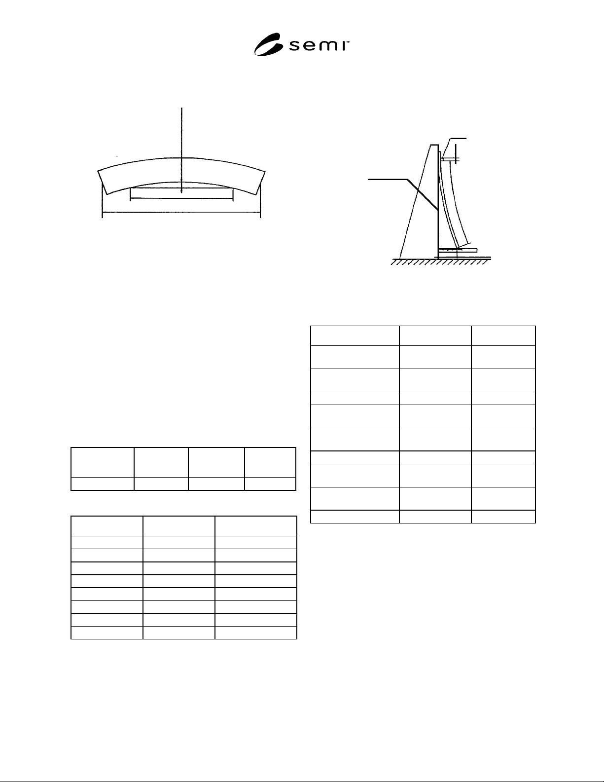
Test Piece
Straight Edge 1000 mm
Length of Strip 1200 mm
Camber (max.)
Figure 1
Camber
5.6.1 Coil Set (Longitudinal Curl)
5.6.1.1 Coil set shall be measured by attaching a length
of strip, appropriate to the country or area of material
origin, to a flat vertical surface as shown in Figure 2.
The attachment shall be with a rigid block, wider than
the strip. The block shall be so rigid as to ensure
complete contact of the strip with the vertical surface.
The distance between the flat surface and the free-
hanging end of the strip (that is positioned for
maximum distance from the flat vertical surface) shall
be measured. The coil set shall be uniformly in the
direction of coiling. Lengths shall be appropriate to the
country or area of material origin. Maximum coil set for
appropriate lengths are shown in Tables 9 and 10.
Table 9
Inside Diame
ter of Coil
Thickness
Width
Max Coil
Set in 1 m
400 mm under 0.3 mm under 100 mm 100 mm
Table 10
Thickness Width Max Coil Set in 0.3 m
Under 0.3 mm up to 15 mm 60 mm
over 15 to 24 mm 50 mm
over 24 to 55 mm 45 mm
over 55 to 100 mm 40 mm
0.3 mm to 0.5 mm up to 15 mm 70 mm
over 15 to 24 mm 60 mm
over 24 to 55 mm 55 mm
over 55 to 100 mm 50 mm
* Table 10 is used in Europe.
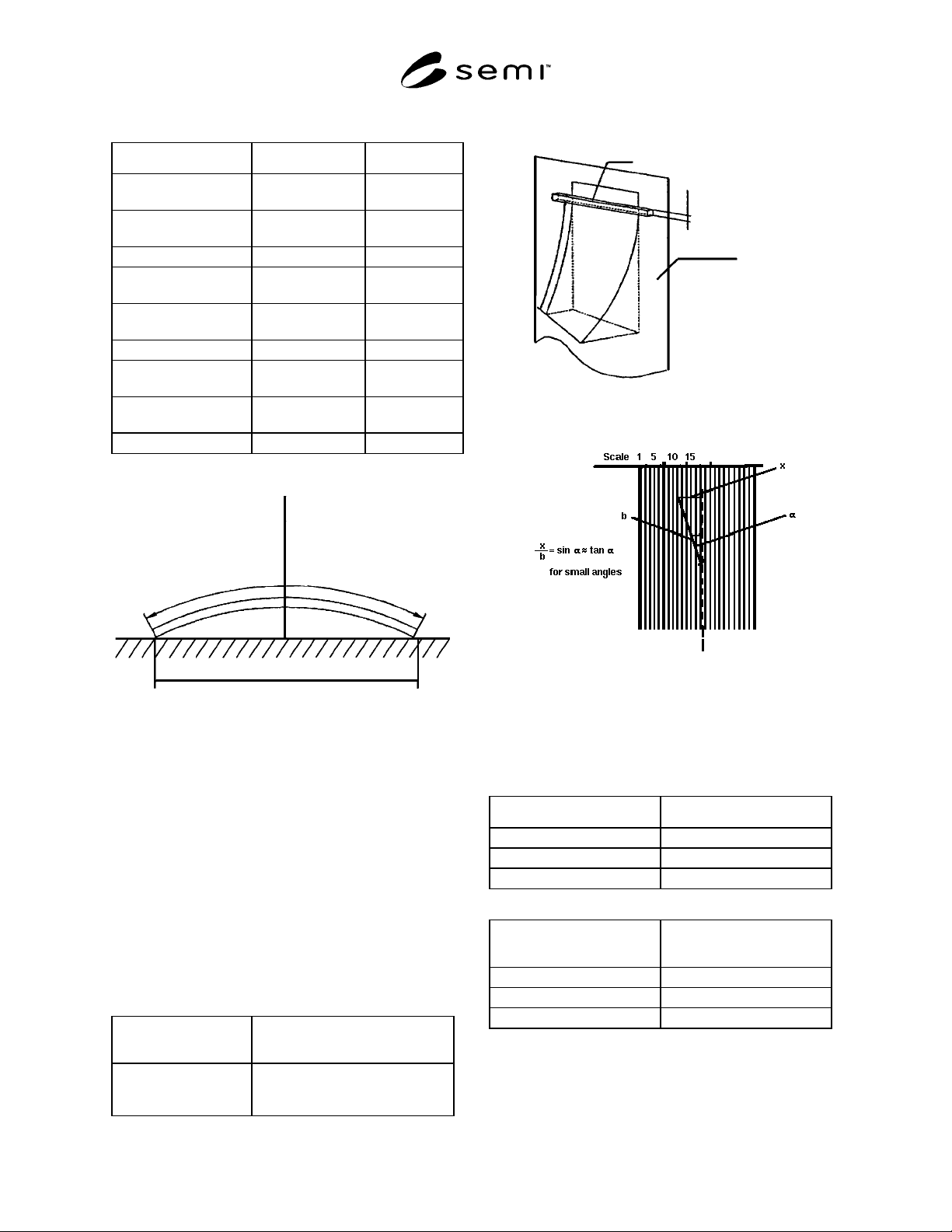
5.6.2 Crossbow (Dish)
5.6.2.1 Crossbow shall be measured across the width of
the strip, as shown in Figure 3. Burrs shall be removed
or burr height excluded from this measurement.
Crossbow shall be measured with a tool maker’s
microscope or equivalent. Crossbow maxima are listed
in Tables 11 and 12.
Flat Vertical
Surface
Block
Coil Set
20 mm
1000 mm
Figure 2
Coil Set
Table 11
Width Thickness Crossbow Limit
under 15 mm 0.1 mm to under
0.3 mm
0.5% of width
0.3 mm to under
1.0 mm
1.0% of width
1.0 mm to 2.0 mm 1.5% of width
15 mm to 55 mm 0.1 mm to under
0.3 mm
0.5% of width
0.3 mm to under
1.0 mm
0.5% of width
1.0 mm to 2.0 mm 0.5% of width
over 55 mm to 100 mm 0.1 mm to under
0.3 mm
0.4% of width
0.3 mm to under
1.0 mm
0.4% of width
1.0 mm to 2.0 mm 0.4% of width
SEMI G4-0302 © SEMI 1982, 2002 5
Table 12
Width Thickness Crossbow Limit
from 15 mm to 24 mm 0.1 mm to under
0.3 mm
0.10 mm
0.3 mm to under
1.0 mm
0.15 mm
1.0 mm to 2.0 mm 0.20 mm
over 24 mm to 55 mm 0.1 mm to under
0.3 mm
0.15 mm
0.3 mm to under
1.0 mm
0.20 mm
1.0 mm to 2.0 mm 0.25 mm
over 55 mm to 100 mm 0.1 mm to under
0.3 mm
0.25 mm
0.3 mm to under
1.0 mm
0.30 mm
1.0 mm to 2.0 mm 0.35 mm
* Table 12 is used in Europe.
Crossbow (max)
Maximum depth, d
Entire width, w
Seeming width, w
s
AB
Figure 3
Crossbow
5.6.3 Twist
5.6.3.1 Twist shall be measured in a fashion similar to
coil set, as shown in Figure 4A or Figure 4B. A length
of strip, appropriate to the country or area of material
origin, shall be attached at one end to a flat vertical
surface. The attachment shall be with a rigid block,
wider than the strip. The block shall be so rigid as to
ensure complete contact of the strip with the vertical
surface. At the free end of the strip, the distance from
the vertical surface and both edges of the free strip end
shall be measured. The maximum difference in these
dimensions is shown in Table 13.
Table 13
Thickness Twist Maximum (Difference in
Edge Distance)
0.1 mm to 0.5 mm Width × 0.2823 for
1000mm (Width × 0.2823
for 300mm)
* Value in parentheses is used in Europe.
Block
Flat Vert
Surface
20 mm
1000 mm
Figure 4
Twist Test
Figure 4B
Twist Test
5.7 Burrs
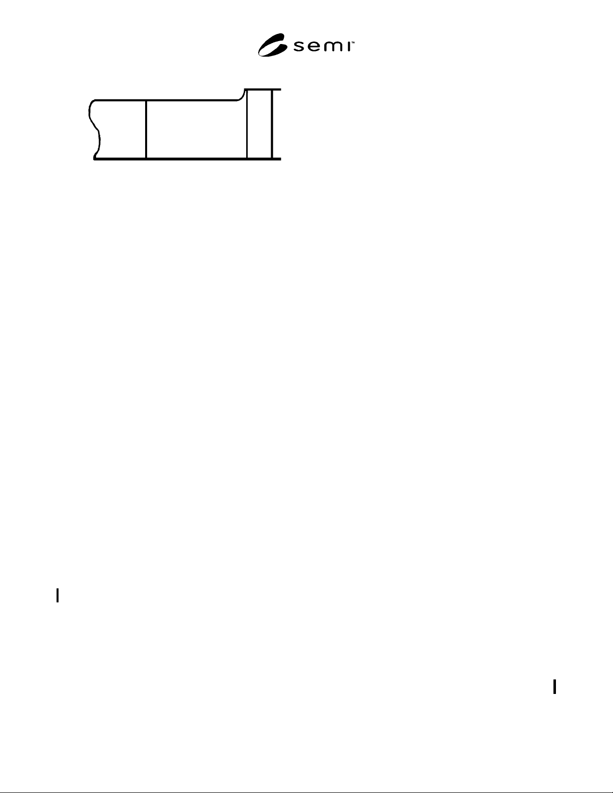
5.7.1 Edge burrs shall not exceed the values in Table
14 and 15. As shown in Figure 5, a-b shall be measured.
Table 14
Thickness Maximum Allowed Edge Burr
0.1 mm to under 0.3 mm Thickness x 10%
0.3 mm to under 1.0 mm Thickness x 7%
1.0 mm to under 2.0 mm Thickness x 5%
Table 15
Thickness
Maximum Allowed Edge
Burr Height
0.1 mm to 0.3 mm 0.02 mm
Over 0.3 mm to 1.0 mm 0.03 mm
Over 1.0 mm to 2.0 mm 0.04 mm
* Table 15 is used in Europe.
SEMI G4-0302 © SEMI 1982, 2002 6
Burr
b
a
Figure 5
Burr
5.8 Corrosion
5.8.1 Visual inspection shall be performed within 60
days of receipt of material. The material shall be free of
objectionable surface oxides which would render the
product unusable for the intended application. The
material shall have been stored for this period in the
original supplier’s package.
6 Bend Formability
6.1 When agreed between supplier and purchaser, a
bend formability test shall be performed. This test shall
be based on area standards based on country or area of
material origin.
6.1.1 Europe ISO 7438 — (Test jig is shown in Figure
2 of ISO 7438.)
6.1.2 Japan CES M0002-5 — The test piece which
shall be 10 mm wide and a minimum of 30 mm long
will be put on the B type test jig with a bend radial of
0.15 mm and 0.25 mm and from 0–2.0 mm at interval
of 0.2 mm. In this case, die pressure shall be 807N
(1000Kgf) and over. The B type test jig is shown in
Figure 2 of CES M0002-5.
6.1.3 United States — ASTM E 290.
7 Lead Bend Fatigue
7.1 When agreed between supplier and purchaser, a
lead bend fatigue test shall be performed. This test shall
be conform to the appropriate area standards based on
the country or area of material origin.
7.1.1 Europe — MIL-STD-883.
7.1.2 Japan — Appendix 1
7.1.3 United States — MIL-STD-883.
8 Physical Properties
8.1 When agreed between supplier and purchaser, tests
on physical properties shall be performed based on
appropriate area standards based on country or area of
material origin.
8.1.1 Chemistry
8.1.1.1 Chemical analysis of material shall be
performed using accepted procedures such as X-Ray
fluorescence spectroscopy, optical emission spectro-
scopy, and atomic absorption spectroscopy. These tests
shall be performed based on appropriate area standards
based on country or area of material origin.
8.1.1.1.1 Europe — ISO.
8.1.1.1.2 Japan — JIS.
8.1.1.1.3 United States — ASTM standards under
preparation.
8.1.2 Electrical Conductivity
8.1.2.1 The test for electrical resistivity and conduct-
ivity shall be performed based on appropriate area
standards based on country or area of material origin.
8.1.2.1.1 Europe — ASTM B193.
8.1.2.1.2 Japan — JIS H0505.
8.1.2.1.3 United States — ASTM B193.
8.1.2.2 Thermal conductivity shall be calculated from
electrical conductivity using the law of Wiedemann and
Franz, which is described as:
k/σT = L, where:
k = thermal conductivity
σ = electrical conductivity
T = absolute temperature
L = Lorenz number = 2.44 × 10
-8
(V/K)
2
where : V = voltage and K = Kelvin scale
8.1.3 Coefficient of Thermal Expansion
8.1.3.1 T he coefficient of thermal expansion shall be
measured between 20°C and 300°C. The test shall be
based on the appropriate area standard based on the
country or area of material origin.
8.1.3.1.1 Europe — ASTM E 228.
8.1.3.1.2 Japan — ASTM E 228.
8.1.3.1.3 United States — ASTM E 228.
9 Silt Strain (Stress)
9.1 When agreed upon between supplier and purchaser,
a test to determine internal stress distribution shall be
performed. The test should be based on some form of
chemical milling, sawing, or wire cutting to remove
portions of the strip to form a pattern in the strip. As a
guide to preparation of such tests, a procedure is shown
in Appendix 2 or 3.