semi合集-English.pdf - 第6945页
SEMI S8-0705 © SEMI 1995, 2005 42 Section 2: Product Load ing in a Standing Posture Section Indicator Figure 2.1 Clearance provided for finger thickness. Acceptance criterion: m inimum 38 mm (1.5 in. ) NOTE: Minimum clea…
SEMI S8-0705 © SEMI 1995, 2005 41
RELATED INFORMATION 7
SEMI S8 SUPPLIER ERGONOMIC SUCCESS CRITERIA (SESC)
CHECKLIST APPLICATIONS GUIDE
NOTICE: This related information is not an official part of SEMI S8 and was derived by the EHS Ergonomics
Task Force. This related information was approved for publication by full letter ballot on September 3, 2003.
R7-1 Purpose
R7-1.1 This section is provided as a companion to the SEMI S8 Supplier Ergonomic Success Criteria (SESC)
checklist as an aid to help equipment designers and evaluators understand how to apply the checklist when designing
equipment or assessing machine designs or prototypes.
R7-1.2 This applications guide follows the numbering scheme of the SESC checklist. When appropriate, notes,
illustrations and diagrams have been added to clarify each item.
NOTE R7-1: For the purpose of this document, “weight” is defined as the force of gravity and units are specified in Newtons (N),
and pound-force (lbf.). One lbf. is the force of gravity on a one-pound mass (lb.) and 9.81 N is the force of gravity on a one-
kilogram mass (kg.).
Table R7-1 Supplier Ergonomic Success Criteria Checklist Applications Guide
Section 1: Manual Material Handling
Section Indicator
1.1 Potentially hazardous manual material handling tasks performed as part of operations, maintenance, or service are
analyzed utilizing appropriate procedures.
NOTE: Two hand lifting or lowering tasks should be analyzed:
if the object being handled weighs more than 44.5 N (10 lbf);
OR, if the object weighs more than 22.2 N (5 lbf) and the anticipated frequency is greater than 1 lift every 5 minutes.
See Appendix 2 for further information.
Acceptance criterion: Analysis and results documentation. Table A2-2, Appendix 2, or the equivalent, should be used
to document 2-hand lift/lower analysis.
Section 2: Product Loading in a Standing Posture
Section Indicator Figure
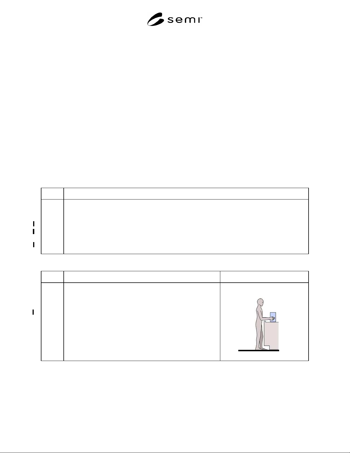
2.0 Product Loading in a Standing Posture (Applicable to all media other
than wafer cassettes including JEDEC trays, magazines and reticle
cassettes.
NOTE A: The criteria of this section should be applied only to production
operations where media will be loaded and unloaded by people.
NOTE B: This guideline may also be applied to manually loaded FOUPs.
NOTE C: A load port is the surface upon which the machine operator
places the media or the base of the media when it is placed on a machine
arm or in a receptacle.
NOTE D: Coupling point is the center of a handle or the center of the
large middle knuckle of the hand when it grasps an object.
SEMI S8-0705 © SEMI 1995, 2005 42
Section 2: Product Loading in a Standing Posture
Section Indicator Figure
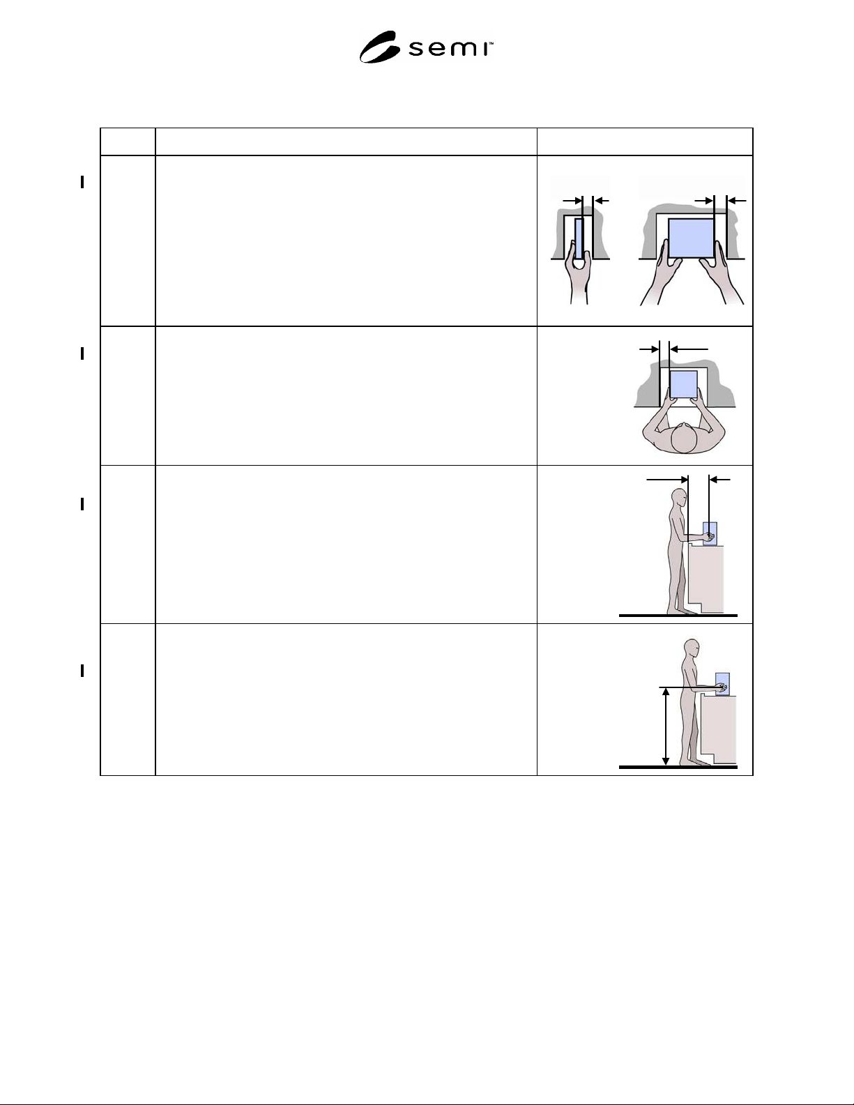
2.1 Clearance provided for finger thickness.
Acceptance criterion: minimum 38 mm (1.5 in.)
NOTE: Minimum clearance should be provided for the finger
clearance for the hand when it is in the orientation used to
grip the item. If the object is grasped from the sides, there
should be finger clearance on both sides. If the object is
grasped from above and below, such as when inserting or
removing a reticle container, there should be minimum finger
clearance above and below the object.
Finger clearance
Minimum 38 mm
(1.5 in.)
One hand Two hands
2.2 Clearance provided for hand thickness.
Acceptance criterion: minimum 76 mm (3.0 in.)
Hand clearance
Minimum 76 mm
(3.0 in.)
2.3 Reach distance measured from the leading edge of the tool or
obstruction to the hand/product coupling point(s).
Acceptance criterion: maximum 330 mm (13 in.)
NOTE: Reach distances should be measured from the leading edge
of the machine housing or any obstruction between the
machine operator and the load port. Obstructions include
keyboard trays, drip trays, anti-vibration platforms and
machine load-bearing pads.
Reach distance
Maximum 330 mm
(13 in.)
2.4 Vertical coupling point of hand to product in load position.
Acceptance criteria: maximum 1010 mm (40 in.)
minimum 890 mm (35 in.)
NOTE: Machine height variables such as the presence of load-
bearing pads, anti-vibration platforms, casters or the
adjustment of leveling feet should be specified when
measuring the load port height.
Vertical coupling
Maximum 1010 mm
(40 in.)
Minimum 890 mm
(35 in.)
SEMI S8-0705 © SEMI 1995, 2005 43
Section 3: Wafer Cassette Loading
Section Indicator Figure
3.0 NOTE A: The criteria of this section should only be applied to
production operations where production materials will be
loaded and unloaded by people.
NOTE B: A load port is the surface upon which the machine operator
places the wafer cassette or the base of the wafer cassette
when it is placed on a machine arm or in a receptacle.
NOTE C: Coupling point is the center of a handle or the large middle
knuckle of the hand when it grasps an object.
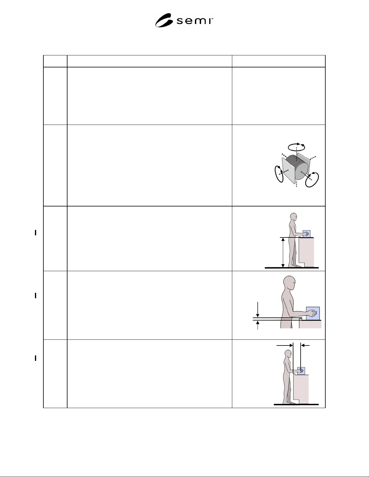
3.1 Wafer cassette loading should not require greater than 10 degrees cassette
rotation about any axis. Unless otherwise specified, you should assume
that 200 mm or smaller wafers are transported in the vertical orientation
and that 300 mm wafers are transported in the horizontal orientation.
Acceptance criteria: less than 10 degrees rotation about any axis.
NOTE: Manual and powered wafer cassette rotation devices are a
means to provide controlled rotation of wafer cassettes. See
section 5.0, “Manual Wafer Cassette Rotation Device
Design” for design recommendations.
Wafer cassette shown in the manual
carrying orientation
Rotation about
the Z-axis
Maximum 10
0
Rotation about the Y-axis
Maximum 10
0
Rotation about
the X-axis
Maximum 10
0
3.2 Load port height, vertical distance from standing surface (150–200 mm
wafers).
Acceptance criteria: maximum 960 mm (38 in.)
minimum 890 mm (35 in.)
NOTE: Machine height variables such as the presence of load
bearing pads, anti-vibration platforms, casters or the
adjustment of leveling feet should be specified when
measuring the load port height.
Maximum 960 mm
(38 in)
Minimum 890 mm
(35 in.)
3.3 Maximum lip height in front of cassette load port over which the cassette
is lifted (150–200 mm wafer cassettes only). Measure lip height from the
load surface.
Acceptance criterion: maximum 30 mm (1.2 in.)
NOTE: For machines where the wafer cassette is loaded on a
machine arm, measure the vertical distance from the base of
the wafer cassette when it’s on the arm to the highest
obstruction the wafer cassette must be lifted over when
loading or unloading.
Lift-over lip
height above the
load port
Maximum 30 mm
(1.2 in.)
3.4 Reach distance from the leading edge of the tool or obstruction to the
coupling point(s) on a rotation device or the product grasp point.
Acceptance criterion: maximum 330 mm (13 in.)
NOTE: Reach distances should be measured from the leading edge of
the machine housing or any obstruction between the machine
operator and the load port. Obstructions include keyboard
trays, drip trays, anti-vibration platforms and machine load-
bearing pads.
Reach distance
Maximum
330 mm
(13 in.)