semi合集-English.pdf - 第193页
SEMI E23-1104 © SEMI 1991, 2004 11 RELATED INFORMATION 3 INTERFACING CIRCUIT EXAMPLES NOTICE: These examples of interfa cing circuit examples are not an offi cial part of this document a nd is not intended to modify or s…
SEMI E23-1104 © SEMI 1991, 2004 10
R2-2
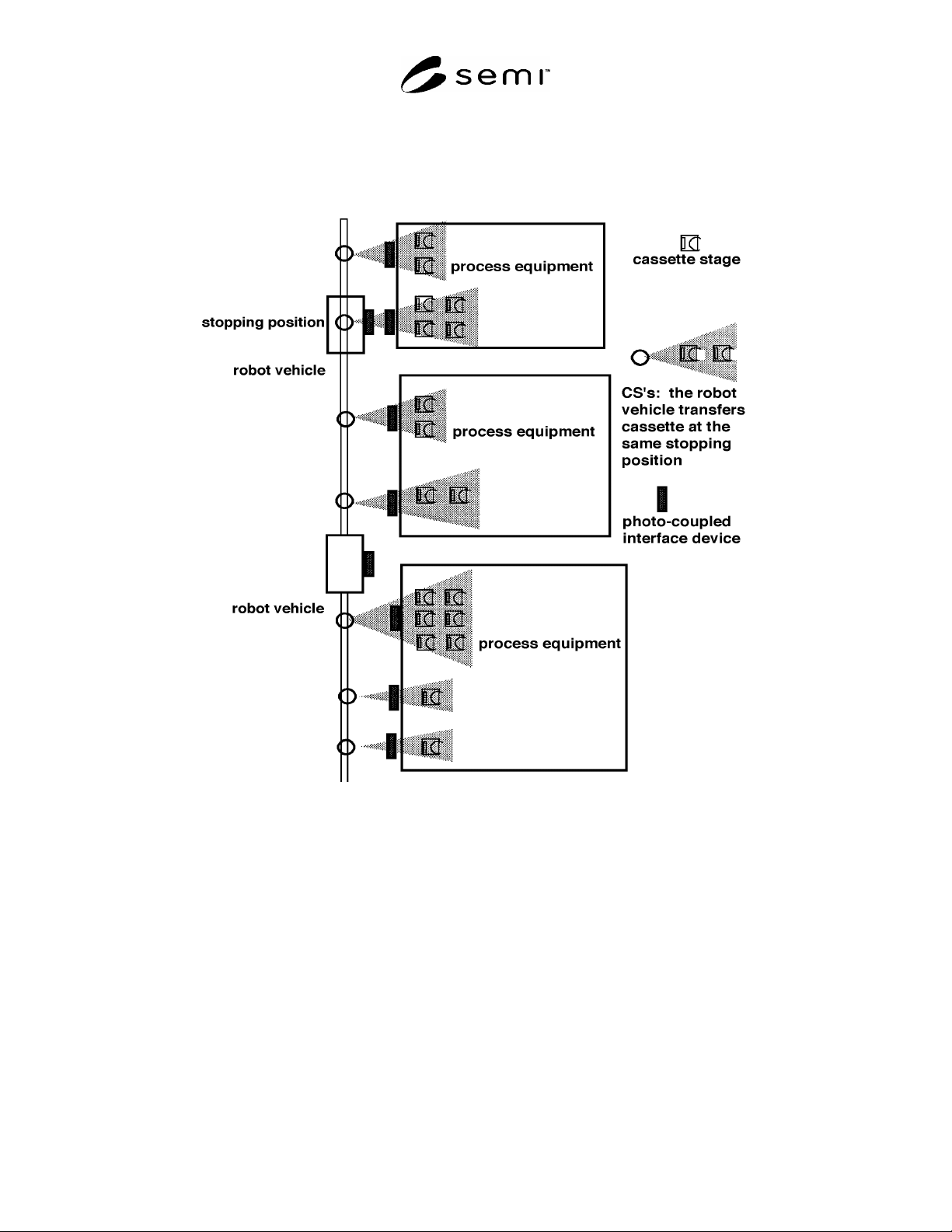
R2-2.1 Figure R2-2 shows some application examples for the photo-coupled parallel I/O interface. One connector is
provided for the CS’s to or from which the robot vehicle transfers a cassette at the same stopping position.
Figure R2-2
Application Example of the Photo-Coupled I/O Interface
SEMI E23-1104 © SEMI 1991, 2004 11
RELATED INFORMATION 3
INTERFACING CIRCUIT EXAMPLES
NOTICE: These examples of interfacing circuit examples are not an official part of this document and is not intended to modify
or supercede the official standard. Determination of the suitability of the material is solely the responsibility of the user.
R3-1
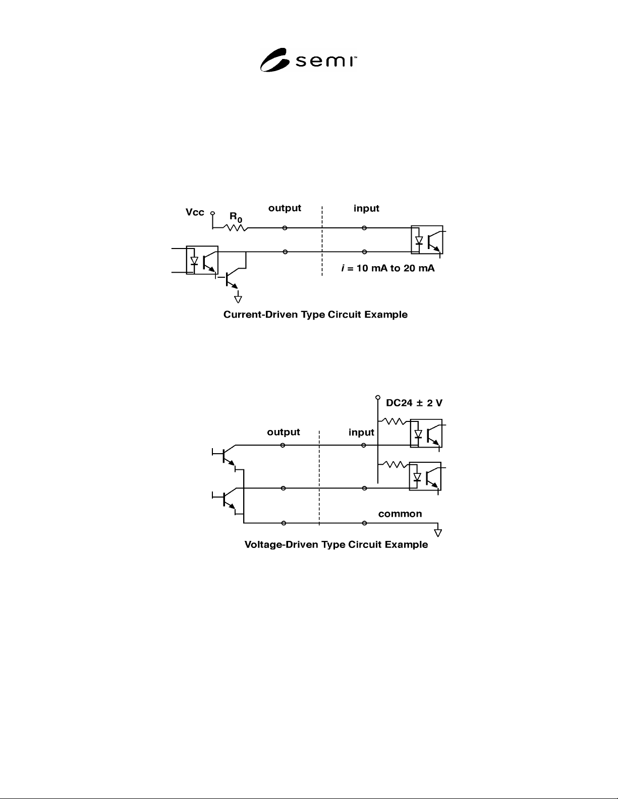
R3-1.1 Figure R3-1 shows typical examples of the two types of the interface circuits for the wire-connected
interface.
Figure R3-1
Interface Circuit Examples for Wire-Connected Interface
NOTICE: SEMI makes no warranties or representations as to the suitability of the standards set forth herein for any
particular application. The determination of the suitability of the standard is solely the responsibility of the user.
Users are cautioned to refer to manufacturer’s instructions, product labels, product data sheets, and other relevant
literature respecting any materials mentioned herein. These standards are subject to change without notice.
The user’s attention is called to the possibility that some implementations of this standard may involve use of
inventions covered by U.S. patents 4,306,292 and other patents issued or pending, held by Texas Instruments
Incorporated. By publication of this standard, SEMI takes no position respecting either the applicability or the
validity of these or other patent rights asserted in connection with any item mentioned in this standard. Users of this
standard are expressly advised that determination of any such patent rights, and the risk of infringement of such
rights, are entirely their own responsibility.
Copyright by SEMI® (Semiconductor Equipment and Materials
International), 3081 Zanker Road, San Jose, CA 95134. Reproduction of
the contents in whole or in part is forbidden without express written
consent of SEMI.

SEMI E24-92 © SEMI 1992, 2004 1
SEMI E24-92 (Reapproved 0704)
CLUSTER TOOL MODULE INTERFACE: ISOLATION VALVE
INTERLOCKS STANDARD
This standard was technically reapproved by the Global Physical Interfaces & Carriers Committee and is the
direct responsibility of the North American Physical Interfaces & Carriers Committee. Current edition
reapproved by the North American Regional Standards Committee on April 22, 2004. Initially available at
www.semi.org June 2004; to be published July 2004. Originally published in 1992.
1 Purpose
1.1 The purpose of this standard is to prevent any
opening or closing of the isolation valve(s) which
would result in an unsafe condition or possible damage
to material or equipment.
1.2 Impact — This standard requires cluster tool
module suppliers to implement the interlock and to
define the conditions that trip the interlock.
2 Scope
2.1 This standard requires hardware inter-locks that
govern the opening and closing of the environmental
isolation valve(s) at the interface planes of a cluster
tool. This standard applies to all modules of a cluster
tool (as defined in SEMI E21).
NOTICE: This standard does not purport to address
safety issues, if any, associated with its use. It is the
responsibility of the users of this standard to establish
appropriate safety and health practices and determine
the applicability of regulatory or other limitations prior
to use.
3 Referenced Standards
3.1 SEMI Standards
SEMI E21 — Cluster Tool Module Interface:
Mechanical Interface and Wafer Transport Standard
3.2 Other Documents
MIL-C-26500E
1
— General Specification for
Connectors — General Purpose, Electrical, Miniature,
Circular, Environmental Resisting
NOTICE: Unless otherwise indicated, all documents
cited shall be the latest published versions.
4 Requirements
4.1 Interlock Provision and Use — Each module
joined to another module, across a common interface
plane (as defined in SEMI E21), must provide a fail-
1 United States Military Standards, Available through the Naval
Publications and Forms Center, 5801 Tabor Avenue, Philadelphia,
PA 19120-5099, USA. Telephone: 215.697.3321
safe interlock that enables opening and closing of the
isolation valve of the other module. Each module that
has an isolation valve must use the interlock provided
by the module it is joined to across their common
interface plane.
4.2 Interlock Trip — Conditions that trip the interlock
must be defined by the module supplier. (See Section
R1-1.)
4.3 Interlock Logic — The interlock is to consist of
two normally open relays and associated actuation
circuitry in each module. (See Section R1-2.)
4.3.1 First Relay — One relay enables opening of the
isolation valve of the attached module. Contact closure
indicates a safe condition, enabling valve opening.
Contact opening disables valve opening if the valve is
closed. Contact opening does not cause the valve to
close if the valve is open. (See Section R1-3.)
4.3.2 Second Relay — The other relay enables closure
of the isolation valve of the attached module. Contact
closure indicates a safe condition, enabling valve
closure. Contact opening disables valve closure if the
valve is open. Contact opening does not cause the valve
to open if the valve is closed.
4.3.3 Monitoring — Situations can arise where the
module A interlock inhibits an operation of the valve on
module B, when that valve is already in the inhibited
condition. This potential conflict must be detected and
resolved within module B. (See Section R1-3.)
4.4 Contact Rating — The relay contacts shall be rated
for a minimum of 1 A at 24 VDC.
4.5 Wiring — Copper wire used in the interlock circuit
shall be 0.82 mm
2
cross section (18 AWG) or larger.
4.6 Interlock Connectors — Metal shell bayonet-type
connectors are specified per MIL-C-26500E as follows:
MS24265R18B11SN panel mounted receptacles on
each of the modules and MS24266R18B11PN plugs
terminating each end of the cable which interconnects
the interlock receptacles of two connected modules.
4.7 Interlock Connector Pinouts
4.7.1 Receptacle — Pins 2 and 3 of the receptacle are
connected across the contacts of the relay specified in