semi合集-English.pdf - 第7164页
SEMI S22-1103a © SEMI 2003, 2005 49 Table A1-13 Creepage an d Clearance in greater than Class 1000 Cl eanroom Basic or Supplementary Insulation Double or Reinforced Insulation Creepage Distance Creepage Distance Installa…
SEMI S22-1103a © SEMI 2003, 2005 48
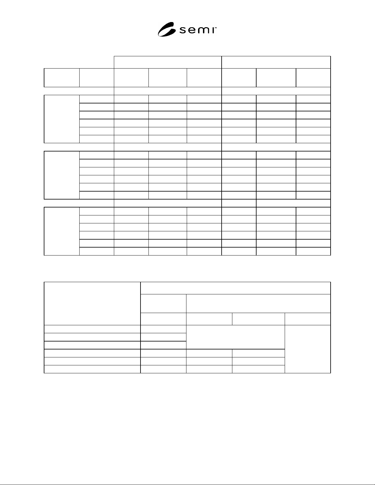
Table A1-12 Creepage and Clearance in Class 1000 or Less Cleanroom
Basic/Supplementary (mm) Double/Reinforced (mm)
Installation
Category
Working
Voltage
Clearance Creepage
Test Voltage,
Vrms
Clearance Creepage
Test Voltage,
Vrms
3
50 0.1 0.18 230 0.10 0.35 400
100 0.1 0.25 350 0.12 0.50 510
150 0.1 0.30 490 0.40 0.60 740
300 0.5 0.70 820 1.60 1.60 140-0
600 1.5 1.70 1350 3.30 3.40 2300
Category 1
1000 3.0 3.20 2200 6.50 6.50 3700
50 0.1 0.18 350 0.12 0.35 510
100 0.1 0.25 490 0.40 0.50 740
150 0.5 0.50 820 1.60 1.60 1400
300 1.5 1.50 1350 3.30 3.30 2300
600 3.0 3.00 2200 6.50 6.50 3700
Category 2
1000 5.5 5.50 3250 11.50 11.50 5550
50 0.1 0.18 490 0.4 0.4 740
100 0.5 0.50 820 1.6 1.6 1400
150 1.5 1.50 1350 3.3 3.3 2300
300 3.0 3.00 2200 6.5 6.5 3700
600 5.5 5.50 3250 11.5 11.5 5550
Category 3
1000 8.0 8.00 4350 16.0 16.0 7400
#1
Specified creepage distances less than 0.70 mm may be reduced on uncoated printed wiring boards according to the following table.
#2
Cleanroom Class 1000 or less is pollution degree 1, however the pollution degree in a particular area in a given piece of equipment may exceed
pollution degree 1, even if the equipment is installed in a cleanroom class 1000 or less.
PWB Creepage Distance
Basic or Supple-
mentary Insulation
Double or Reinforced
Equipment Creepage Distance, mm
Category 1 Category 2 Category 3
0.18 0.1
0.25 0.1
0.30 0.2
No reduction
0.35 0.10 0.12
0.50 0.5 0.20 0.40
0.60 0.45
No reduction
#3
If necessary to test using DC voltage, increase specified test voltage by 42 percent.
SEMI S22-1103a © SEMI 2003, 2005 49
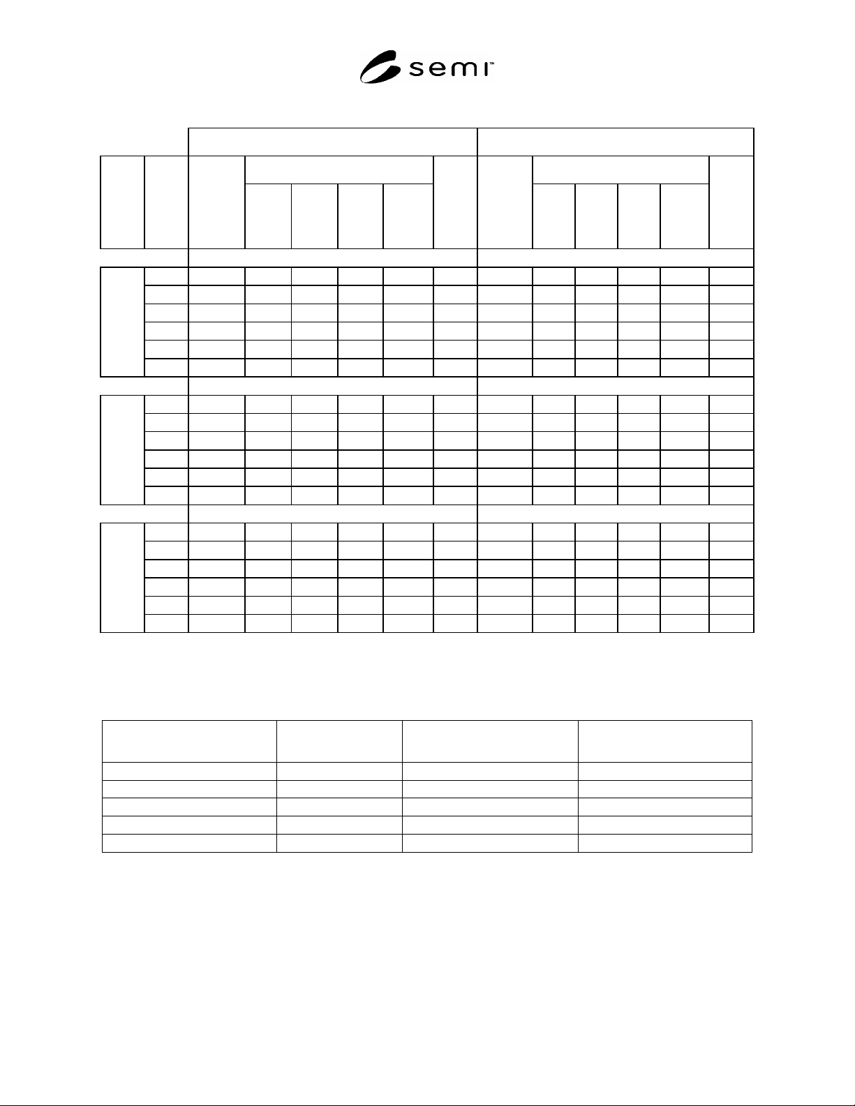
Table A1-13 Creepage and Clearance in greater than Class 1000 Cleanroom
Basic or Supplementary Insulation Double or Reinforced Insulation
Creepage Distance Creepage Distance
Installation
Category
Working Voltage
Clearance
Distance
CTI >
600
CTI >
400
CTI >
100
Printed
Wiring
Board
CTI > 175
Test
Voltage,
rms
1
Clearance
Distance
CTI >
600
CTI >
400
CTI >
100
Printed
Wiring
Board
CTI > 175
Test
Voltage,
rms
1
50 0.2 0.6 0.85 1.2 0.20 230 0.2 1.2 1.7 2.4 0.4 400
100 0.2 0.7 1.00 1.4 0.20 350 0.2 1.4 2.0 2.8 0.4 510
150 0.2 0.8 1.10 1.6 0.35 490 0.4 1.6 2.2 3.2 0.7 740
300 0.5 1.5 2.10 3.0 1.40 820 1.6 3.0 4.2 6.0 2.8 1400
600 1.5 3.0 4.30 6.0 3.00 1350 3.3 6.0 8.5 12.0 6.0 2300
Category 1
1000 3.0 5.0 7.00 7.0 5.00 2200 6.5 10.0 14.0 20.0 10.0 3700
50 0.2 0.6 0.85 1.2 0.2 350 0.2 1.2 1.7 2.4 0.4 510
100 0.2 0.7 1.00 1.4 0.2 490 0.2 1.4 2.0 2.8 0.4 740
150 0.5 0.8 1.10 1.6 0.5 820 1.6 1.6 2.2 3.2 1.6 1950
300 1.5 1.5 2.10 3.0 1.5 1350 3.3 3.3 4.2 6.0 3.3 3250
600 3.0 3.0 4.30 6.0 3.0 2200 6.5 6.5 8.5 12.0 6.5 5250
Category 2
1000 5.5 5.5 7.00 10.0 5.5 3250 11.5 11.5 14.0 24.0 11.5 7850
50 0.2 0.6 0.85 1.2 0.2 490 0.4 1.2 1.7 2.4 0.4 740
100 0.5 0.7 1.00 1.4 0.5 820 1.6 1.6 2.0 2.8 1.6 1950
150 1.5 1.5 1.50 1.6 1.5 1350 3.3 3.3 3.3 3.3 3.3 3250
300 3.0 3.0 3.00 3.0 3.0 2200 6.5 6.5 6.5 6.5 6.5 5250
600 5.5 5.5 5.50 6.0 5.5 3250 11.5 11.5 11.5 12.0 11.5 7850
Category 3
1000 8.0 8.0 8.00 10.0 8.0 4350 16.0 16.0 16.0 20.0 16.0 10450
#1
If necessary to test using DC voltage, increase specified test voltage by 42 percent.
#2
Cleanroom Class greater than 1000 is pollution degree 2, however the pollution degree in a particular area in a given piece of equipment may
exceed pollution degree 2, even if the equipment is installed in a cleanroom greater than 1000.
Table A1-14 Over Currrent Protection For Transformers without Thermal Protection
Transformer Primary Rating Transformer Secondary
Rating
Maximum Primary Protection
Percent Of Rating (See Note 1)
Maximum Secondary Protection
Percent Of Rating
#1
Any Rating 9 amperes or more 250 125
Any Rating Less than 9 amperes 250 167
9A or more Any Rating 125 Not Required
Less than 9A and more than 2A Any Rating 167 Not Required
2A or less Any Rating 300 Not Required
#1
Where the rating does not match a standard overcurrent device rating, the next standard size is permitted.

SEMI S22-1103a © SEMI 2003, 2005 50
Table A1-15 Over Current Protection For Transformers with Thermal Protection
Transformer Impedance Maximum Primary Protection
Percent Of Rating (See Note 1)
Maximum Secondary Protection
Percent Of Rating
#1
6 percent or Less 600 125
More than 6 percent and Less Than
10 percent
400 125
#1
Where the rating does not match a standard overcurrent device rating, the next standard size is permitted.
NOTICE: SEMI makes no warranties or representations as to the suitability of the safety guidelines set forth herein
for any particular application. The determination of the suitability of the safety guidelines is solely the
responsibility of the user. Users are cautioned to refer to manufacturer's instructions, product labels, product data
sheets, and other relevant literature, respecting any materials or equipment mentioned herein. These safety
guidelines are subject to change without notice.
By publication of this safety guideline, Semiconductor Equipment and Materials International (SEMI) takes no
position respecting the validity of any patent rights or copyrights asserted in connection with any item mentioned in
this safety guideline. Users of this guideline are expressly advised that determination of any such patent rights or
copyrights, and the risk of infringement of such rights are entirely their own responsibility.