semi合集-English.pdf - 第61页
SEMI E6-0303 © SEMI 1982, 2003 7 10.2.18 Other Conditions (200R) — Include in other any special environmental cond itions such as lighting, ESD, electromagnetic, or audib le noise conditions for the equipment components.…

SEMI E6-0303 © SEMI 1982, 2003 6
10 Environmental Conditions Data Sheet
10.1 Include in Data Sheet 200, Environmental
Conditions, requested information for the
environmental conditions necessary to operate the
equipment such as room temperature, room humidity,
room cleanliness, heat loading, and vibration. Include
only conditions for area surrounding the equipment, do
not refer to internally controlled specifications for
integrated minienvironments, chambers, or lenses, etc.
10.2 Data Sheet 200, Environmental Conditions,
contains the following items.
10.2.1 Equipment Component (200A) — Enter the
name of the equipment component for the data in this
row. The same component names should be used in the
following data sheets.
10.2.2 Maximum Installation Distance from Mainframe
(200B) — Enter the maximum line of sight or straight
line distance between the mainframe and equipment
component. Also, indicate the limiting factors for this
distance. For example: 6 meters, user routing
constraints may cause distance to be significantly less.
10.2.3 Minimum Cleanroom Classification (200C) —
Enter the minimum cleanroom classification that
defines the cleanroom environment necessary for
equipment to operate correctly.
10.2.4 Cleanroom Classification Standard (200D) —
Enter a reference for the cleanroom classification
standard used to specify the cleanroom class in 200C.
For example: Fed Std 209E or ISO 14644.
10.2.5 Target Room Temperature (200E) — Enter the
optimal temperature setting within the minimum and
maximum ranges for the room where the equipment is
located.
10.2.6 Minimum Room Temperature (200F) — Enter
the minimum room temperature for the equipment to
operate correctly.
10.2.7 Maximum Room Temperature (200G) — Enter
the maximum room temperature for the equipment to
operate correctly.
10.2.8 Room Temperature Fluctuation (200H) — Enter
the maximum room temperature change during one
hour for the equipment to operate correctly.
10.2.9 Heat Loading Idle Average (200I) — Enter the
average heat flow rate in idle condition into the room
where the equipment component is located. Do not
include heat removed by other means such as process
cooling water or exhaust. The room should be at target
temperature and humidity.
10.2.10 Heat Loading Process Average (200J) — Enter
the average heat flow rate during the processing cycle
into the room where the equipment component is
located. Do not include heat removed by other means
such as process cooling water or exhaust. The room
should be at target temperature and humidity.
10.2.11 Target Room Relative Humidity (200K) —
Enter the optimal relative humidity at the target
temperature for the room where the equipment is
located.
10.2.12 Minimum Room Relative Humidity (200L) —
Enter the minimum relative humidity at the target room
temperature for the equipment to operate correctly.
10.2.13 Maximum Room Relative Humidity (200M) —
Enter the maximum relative humidity at the target room
temperature for the equipment to operate correctly.
10.2.14 Room Relative Humidity Fluctuation (200N) —
Enter the maximum relative humidity change during
one hour for the equipment to operate correctly.
10.2.15 Vibration Sensitivity (200O) — Enter the
vibration requirements or reference a document
specifying the ambient vibration sensitivity and ambient
acoustic noise sensitivity of the equipment. Include in
reference material the description of methods used such
as displacement, 1/3 octave band analysis, accelerance,
maximum velocity at frequency, maximum ambient
sound pressure levels, etc.
10.2.16 Vibration Generation (200P) — Enter the
vibration generated by the equipment that stimulates the
mounting structure or reference a document defining
the equipment generated dynamic loads (at the support
points defined in the floor loading diagram—see
Section 11.2.10) such as impulse force magnitudes in
the front-to-rear direction, etc. Include in reference
material the description of methods used such as
spectral accelerometer measurements of the equipment
mounted on a pedestal of specified stiffness, etc.
Include equipment-generated acoustic noise, such as the
sound pressure level spectra radiated outward from the
equipment enclosure.
10.2.17 Other Vibrations Requirements (200Q) —
Enter or reference any other equipment support
vibration requirements such as support pedestal
stiffness requirements in all three directions, coupled
mass requirements, or minimum building structural
stiffness (three axis x, y, z) requirements.
NOTE 5: Vibration sensitivity and generation values for
dynamic loads and motions should be specified in the three
directions: up and down (z), front to back (y), and side to side
(x).
SEMI E6-0303 © SEMI 1982, 2003 7
10.2.18 Other Conditions (200R) — Include in other
any special environmental conditions such as lighting,
ESD, electromagnetic, or audible noise conditions for
the equipment components.
10.2.19 Environmental Conditions Comments (200S)
— Enter any comments necessary to clarify or add to
information given for this equipment component.
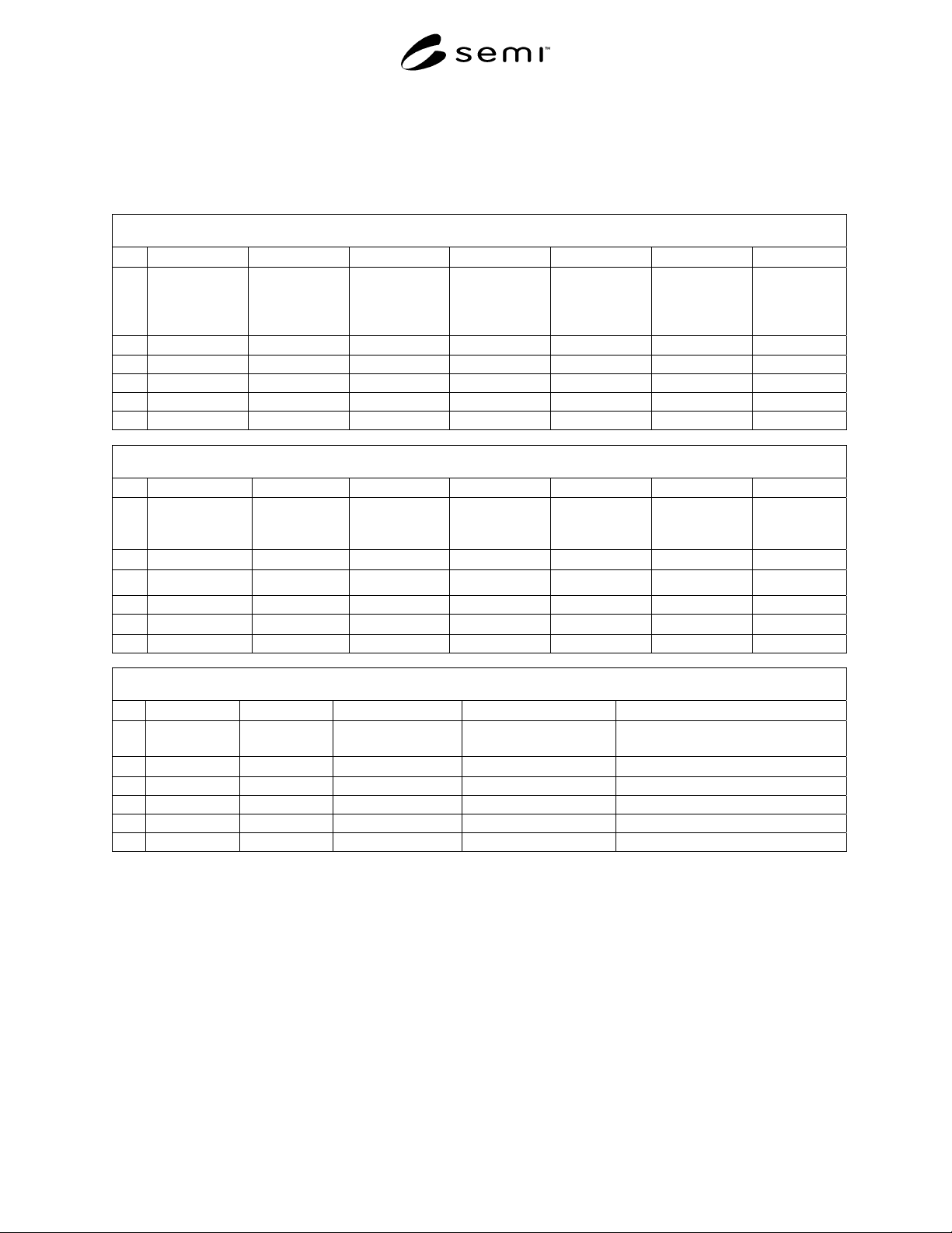
Data Sheet 200 – Environmental Conditions (See SEMI E6 Section 10)
200 Environmental Conditions
A B C D E F G
1
Equipment
Component
Maximum
Installation
Distance from
Mainframe
Minimum
Cleanroom
Classification
Cleanroom
Classification
Standard
Target Room
Temperature
Minimum Room
Temperature
Maximum
Room
Temperature
2
text meters text text degrees C degrees C degrees C
3
4
5
6
200 Environmental Conditions
H I J K L M N
1
Room
Temperature
Fluctuation
Heat Loading
Idle Average
Heat Loading
Process Average
Target Room
Relative
Humidity
Minimum Room
Relative
Humidity
M
aximum Room
Relative
Humidity
Room Relative
Humidity
Fluctuation
2
degrees /hour watts watts % % % %/hour
3
4
5
6
200 Environmental Conditions
O P Q R S
1
Vibration
Sensitivity
Vibration
Generation
Other Vibrations
Requirements
Other Conditions Environmental Conditions Comments
2
text text text text text
3
4
5
6

SEMI E6-0303 © SEMI 1982, 2003 8
11 Physical Characteristics Data Sheet
11.1 Include in Data Sheet 300, Physical
Characteristics the requested information for physical
attributes such as size, weight, layout, clearances, and
floor loading data.
11.2 Data Sheet 300, Physical Characteristics contains
the following items.
11.2.1 Equipment Component (300A) — Enter the
name of the equipment component for the data in this
row. The name should be the same name used in Data
Sheet 200.
11.2.2 Shipping and Receiving Information Reference
(300B) — Enter reference for document containing all
relevant shipping and receiving information. (See
Section 7.1.2 and Related Information 2.)
11.2.3 Number of Shipping Containers (300C) — Enter
the total number of containers or crates used to ship the
equipment and all supplier provide support equipment.
11.2.4 Move-in, Placement and Assembly Instructions
Reference (300D) — Enter reference for document
containing all installation instruction. (see Section 7.1.3
and Related Information 3.)
11.2.5 Number of Cleanroom Move-in Pieces (300E)
— Enter the total number of pieces of equipment to be
moved into the manufacturing cleanroom.
11.2.6 Biggest Move-in Piece Length, Width, Height,
Weight (300F, 300G, 300H, 300I) — Enter the size and
weight of the largest single move-in piece of the
equipment.
11.2.7 Installation ESH Information Reference (300J)
— Enter reference for document containing all relevant
environmental, safety, and health information related to
equipment installation. (See related SEMI Safety
Guidelines)
11.2.8 Assembled Length, Width, Min. Height, Max
Height, Weight (300K, 300L, 300M, 300N): 300O) —
Enter the size and weight of the equipment component.
Minimum and maximum height should include travel of
any provided leveling feet.
11.2.9 Operational Clearance Front, Right, Left, Back,
Top Bottom (300P, 300Q, 300R, 300S, 300T) 300U) —
Enter the operational clearances on all sides of
equipment necessary for safety, operation, and
maintenance. (Right and left should be as viewed from
the front)
11.2.10 Floor Loading Diagram Reference (300V) —
Enter the reference for the floor-loading diagram
showing the static weight loads at each equipment
support point.
11.2.11 Drawing References (300W) — Enter
references, such as drawing numbers, for any drawings,
schematics, instructions, jigs or fixtures showing
equipment. For example: Equipment Footprint Drawing
YYYYY. Submit referenced material to equipment
purchaser with this data sheet.
NOTE 6: Information regarding 300mm equipment may be
found in SEMI E72 and SEMI E63.
11.2.12 Physical Conditions Comments (300X) —
Enter any comments necessary to clarify or add to
information given for this equipment component.