semi合集-English.pdf - 第435页
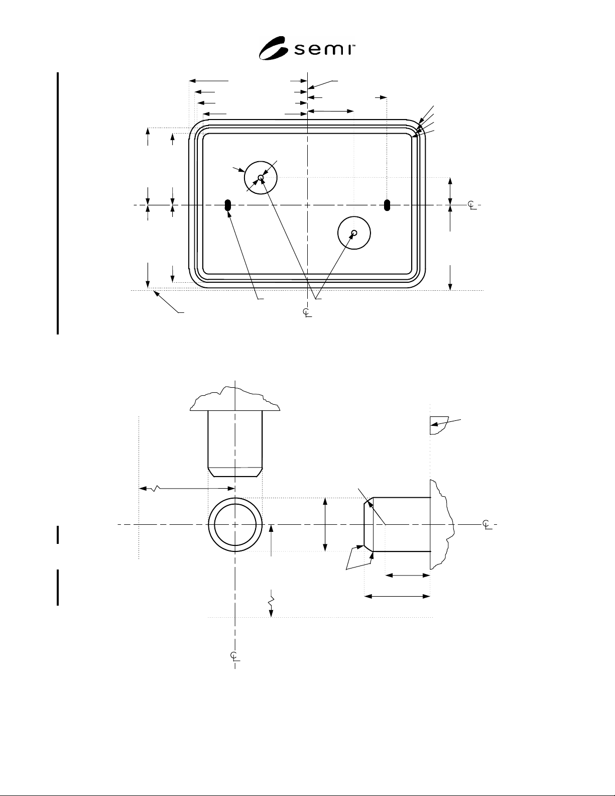
SEMI E62-0705 © SEMI 1997, 2005 4 z 32 84.5 (144.5) z 33 = 93.5 (153.5 ) ± 0 .2 5 z 34 = 95.5 (155.5) ± 0 .2 5 z 35 104.5 (164.5 ) z 31 = 45 (105 ) ± 0 . 1 x 32 173.5 z 30 = 106.5 (166.5 ) bilateral datum plane …

SEMI E62-0705 © SEMI 1997, 2005 3
5.5 Seal Zones — On the exterior side of the port must be two areas for sealing to the box. The door seal zone must
be just inside the rim of the port door in the area between x32 and x33 from the facial datum plane and between z32
and z33 from the vertical center line of the port (which is z30 above the facial datum plane). Similarly, the frame
seal zone must be on the frame of the port door in the area between x34 and x35 from the facial datum plane and
between z34 and z35 from the vertical center line of the port. The door and its frame must be designed to mate with
a front-opening box that conforms to SEMI E47.1. Specifically, the port door and its frame must have surfaces that
mate with the seal zones and the reserved spaces for vacuum application (which includes all of the circles bounded
by r38 except for the holes for the registration pins at the center of each circle). It is recommended that a gap be
maintained between mating surfaces on the box and load port (unless the minienvironment is purged with an inert
gas, in which case a tight seal is recommended).
5.6 Inner and Outer Radii — All required concave features may have a radius of up to r45 to allow cleaning and to
prevent contaminant build-up. All required convex features may also have a radius of up to r46 to prevent small
contact patches with large stresses that might cause wear and particles. Note that these limits on the radius of all
required features are specified as a maximum (not a minimum) to ensure that the required features are not rounded
off too much. The lower bound on the radius is up to the interface supplier. Note also that this radius applies to
every required feature unless another radius is called out specifically.
5.7 Force Between Box and Port — The force with which the load port holds the box in place against the FIMS
interface must be greater than the force with which the load port presses the box door into the box.
5.8 Force Between Box Door and Box — The load port must press the box door into the box with a force of f34.
5.9 Door Return Repeatability — The load port must return the port door to the closed position after opening with a
repeatability given by the dimensions x37 and z37.
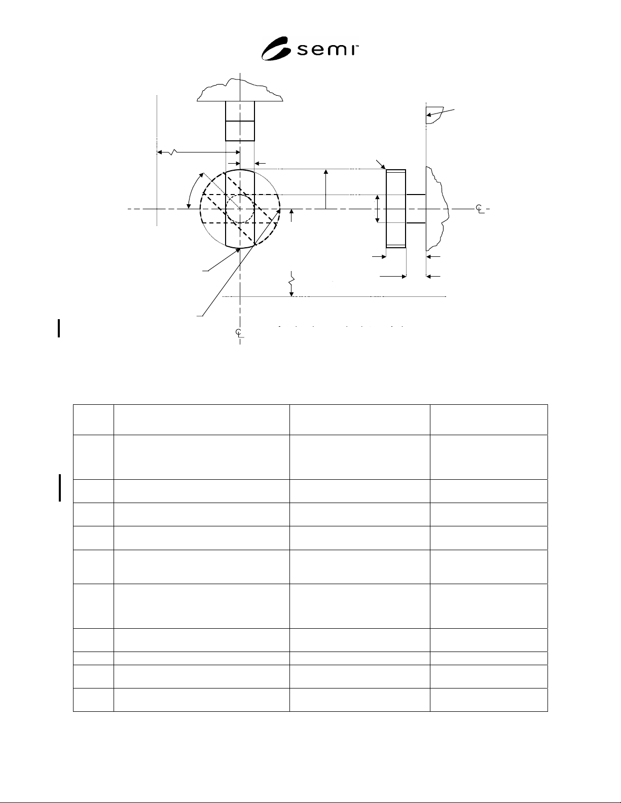
5.10 Force Applied by Latch Keys — If the load port uses retracting latch keys, once the latch keys have been
turned to the position that unlocks the box door from the box ( = 0 ± 1°), the force (in a direction perpendicular to
the facial datum plane) applied by each latch key to the FOUP door must be no greater than f35.
5.11 Door Accommodation — The load port must mate completely with the box at the FIMS interface. One method
to accomplish this is to have the load port door protrude sufficiently (with some cushioning ability) to meet the
FOUP door (however far the FOUP door protrudes within what SEMI E47.1 allows). The load port door (at least on
the seal zone plate) must also accommodate variations in angle (with respect to the Facial Datum Plane) of the
FOUP door (however much the FOUP door varies in angle within what SEMI E47.1 allows).
6 Related Documents
6.1 SEMI Standards
SEMI E15.1 — Specification for 300 mm Tool Load Port
SEMI E63 — Mechanical Specification for 300 mm Box Opener/Loader to Tool Standard (BOLTS-M) Interface
SEMI M31 — Provisional Mechanical Specification for Front-Opening Shipping Box Used to Transport and Ship
300 mm Wafers
SEMI E62-0705 © SEMI 1997, 2005 4
z32
84.5
(144.5)
z33
= 93.5
(153.5)
± 0.25
z34
= 95.5
(155.5)
± 0.25
z35
104.5
(164.5)
z31 = 45 (105)
± 0.1
x32 173.5
z 30
= 106.5
(166.5)
bilateral datum plane
load port horizontal datum plane
(numbers in parentheses are for 25-wafer boxes, if different)
latch key
r32 10
r33 = 21 ± 0.25
r34 = 23 ± 0.25
r35 30
x30 = 129 ± 0.1
registration pins
x31
= 70 ± 0.1
x33 = 182.5 ± 0.25
x34 = 184.5 ± 0.25
x35193.5
d31 = 9 ± 0.02
r38 27.5
Figure 1
Dimensions for Front-Opening Interface
y31 = 7.5
(to origin of r30)
y32 =
11 ± 0.1
z31 = 45 (105)
± 0.1
bilateral
datum
plane
center line of the port ( z 30 above the horizontal datum plane)
x31
= 70 ± 0.1
d31=
9 + 0.02 - 0.2
door
seal area
r30 = 5 ± 0.5
= 0.4 ± 0.1
(blend radius)
(numbers in parentheses are
for 25-wafer boxes, if different)
Figure 2
Registration Pin Dimensions
SEMI E62-0705 © SEMI 1997, 2005 5
position when
door is latched to
box
( = 90 ± 1°)
position when
door is unlatched
from box
( = 0 ± 1°)
(numbers in parentheses are for 25-wafer
boxes, if different)
[numbers in square brackets are for boxes
with removable cassettes, if different]
y37= 3.5±0.1
y36= 7±0.1
z30
=106.5
(166.5)
[128
(188)]
d37
=5±0.2
bilateral
datum
plane
load port horizontal datum plane
r36
=6.75±0.1
x36 =2.5±0.1
x30=
129±0.1
door
seal zone
r41=1.5±0.2
(blend radius
at edge of
front surface)
x30 =
129 ± 0.1
x
36 = 2.5 ± 0.1
r41 = 1.5 ± 0.2
(blend radius
at edge of
front surface)
r36
= 6.75 ± 0.1
d37
= 5 ± 0.2
y36 = 7 ± 0.1
y
37 = 3.5 ± 0.1
z30
= 106.5
(166.5)
Figure 3
Latch Key Dimensions
Table 1 Dimensions for Front-Opening Interface Mechanical Specification (FIMS)
Symbol
Used
Value Specified Datum Measured from Feature Measured to
0 ± 1°
(to unlatch the box door from the box)
90 ± 1°
(to latch the box door to the box)
horizontal datum plane clockwise rotation of latch key
d31 9 + 0.02 mm, 0.2 mm
(0.3543 + 0.0008 in. 0.008 in.)
diameter centered on the intersection
of x31 and z31
surface of registration pin shaft
d37 5 ± 0.2 mm
(0.197 ± 0.008 in.)
diameter centered on the intersection
of x30 and z30
surface of latch key shaft
f30 1.7 N-m (15 in.-lbf.) minimum not applicable torque delivered by the port to
turn the latch keys
f34 9 N (2 lbf.) minimum not applicable force with which the port
presses the box door into the
box
f35 20 N (4.5 lbf.) maximum not applicable force per latch key applied to
the FOUP door (in a direction
perpendicular to the facial
datum plane)
r30 5 ± 0.5 mm
(0.20 ± 0.02 in.)
intersection of x31, y31, and z31 shoulder of registration pin
r32 10 mm (0.39 in.) minimum not applicable inside corner of door seal zone
r33 21 ± 0.25 mm
(0.827 ± 0.010 in.)
not applicable outside corner of door seal
zone
r34 23 ± 0.25 mm
(0.906 ± 0.010 in.)
not applicable inside corner of frame seal
zone