semi合集-English.pdf - 第6964页
SEMI S9-1101 © SE MI 1995, 2001 1 SEMI S9-1101 SAFETY GUIDELINE FOR ELECTRICA L DESIGN VERIFICA TION TESTS FOR SEMICONDUCTOR M ANUFA CTURI NG EQUIPMENT This g uideline wa s tec hnically approved by the G lobal Environme …
SEMI S8-0705 © SEMI 1995, 2005 60
Section 10: Workstation Design
Section Indicator Figure
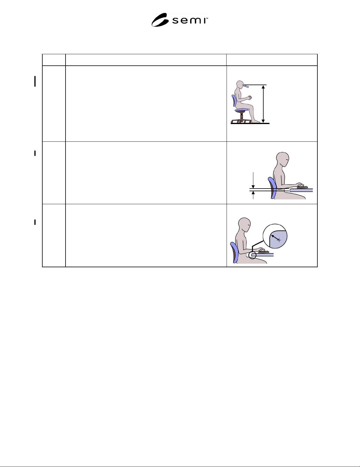
10.2.6 Height of microscope eyepiece. Must be adjustable.
Acceptance criterion: Range includes 1220 mm (48 in.) to 1370 mm
(54 in.)
NOTE A: Measure from the standing surface to center of the eyepiece.
NOTE B: Both height-adjustable eyepieces and adjustable tables may
be used to meet this recommendation. If a height-adjustable
table is used, the SESC checklist should be used to determine
the appropriate machine load port heights, leg clearances, and
the location of controls and displays for the maximum and
minimum table heights.
Microscope
eyepiece heights
Maximum 1370 mm
(54 in.)
Minimum 1220
(48 in.)
10.2.7 Thickness of work surface.
Acceptance criterion: maximum 51 mm (2.0 in.)
Work surface
thickness
Maximum 51
mm
(2.0 in.)
10.2.8 Work surface edge radius where the operator can assume a static posture
in contact with the edge.
Acceptance criterion: minimum 6 mm (0.25 in.) radius
NOTE: This recommendation applies to both horizontal and vertical
surfaces where the equipment operator can assume a static
posture.
Work surface edge radius
Minimum 6.4 mm
(
0.25 in.
)
NOTICE: SEMI makes no warranties or representations as to the suitability of the safety guidelines set forth herein
for any particular application. The determination of the suitability of the safety guidelines is solely the responsibility
of the user. Users are cautioned to refer to manufacturer's instructions, product labels, product data sheets, and other
relevant literature, respecting any materials or equipment mentioned herein. These safety guidelines are subject to
change without notice.
By publication of this safety guideline, Semiconductor Equipment and Materials International (SEMI) takes no
position respecting the validity of any patent rights or copyrights asserted in connection with any item mentioned in
this safety guideline. Users of this guideline are expressly advised that determination of any such patent rights or
copyrights, and the risk of infringement of such rights are entirely their own responsibility.
Copyright by SEMI® (Semiconductor Equipment and Materials
International), 3081 Zanker Road, San Jose, CA 95134. Reproduction of
the contents in whole or in part is forbidden without express written
consent of SEMI.

SEMI S9-1101 © SEMI 1995, 20011
SEMI S9-1101
SAFETY GUIDELINE FOR ELECTRICAL DESIGN VERIFICATION
TESTS FOR SEMICONDUCTOR MANUFACTURING EQUIPMENT
This guideline was technically approved by the Global Environmental Health and Safety Committee and is
the direct responsibility of the North American Environmental Health and Safety Committee. Current edition
approved by the North American Regional Standards Committee on August 27, 2001. Initially available at
www.semi.org September 2001; to be published November 2001. Originally published in 1995.
NOTICE: This document as balloted is intended to
replace SEMI S9-95 in its entirety.
NOTICE: Paragraphs entitled “NOTE” are not an
official part of this document and are not intended to
modify or supercede the official guideline. The task
force has supplied them to clarify and to enhance usage
of the guideline by equipment designers.
1 Purpose
1.1 The purpose of this document is to provide
electrical design verification tests, test methods, and
acceptance criteria for semiconductor manufacturing
equipment. Some of these tests are used as part of the
electrical safety evaluation in SEMI S2.
2 Scope
2.1 This safety guideline should be applied to one or
more representative samples of the equipment (or parts
of the equipment) used for the manufacturing,
measurement, assembly, and testing of semiconductor
products.
2.2 The following tests are discussed in this document:
• Leakage Current Test (Section 9.1)
• Grounding Continuity Test (Section 9.2)
• Starting Current Test (Section 9.3)
• Input Test (Section 9.4)
• Dielectric Test (Section 9.5)
• Strain Relief Test (Section 9.6)
• Transformer Output Short Circuit Test (Section
9.7)
• Power Supply Output Short Circuit Test (Section
9.8)
• Safety Circuit Function Test (Section 9.9)
• Safety Circuits Conductor Disconnection Test
(Section 9.10)
• Capacitor Stored Energy Discharge Test (Section
9.11)
• Temperature Test (Section 9.12)
2.3 This safety guideline does not purport to address all
of the safety issues associated with its use. It is the
responsibility of the user of this safety guideline to
establish appropriate safety and health practices and
determine the applicability of regulatory limitations
prior to use.
3 Limitations
3.1 This document is not intended to be a
comprehensive compilation of electrical tests specified
in product safety standards. This document is also not
intended to replace any test methods described in any
appropriate national or international product safety
standards.
3.2 It is not the intent of this guideline to require
repetition of tests where the equipment has been
certified or tested to other relevant electrical product
safety standards. Any applicable test from this
guideline that has been previously completed under an
applicable product standard and which satisfies the
intent of that test should be accepted, even if there are
differences in test methods.
3.3 Engineering analysis, when based on sound
engineering principles, may serve as an alternative to
conducting a test.
3.4 If it is evident from the design and construction of
the equipment that a particular test is not safety-
relevant, the test need not be performed.
3.5 This document is not intended to address
production line or routine testing.
4 Referenced Standards
4.1 SEMI Standards
SEMI S2 — Environmental, Health, and Safety
Guideline for Semiconductor Manufacturing Equipment

SEMI S9-1101 © SEMI 1995, 2001 2
4.2 IEC Standard
1
IEC 61010-1 — Safety Requirements for Electrical
Equipment for Measurement, Control, and Laboratory
Use, Part 1: General Requirements
NOTE 1: Unless otherwise indicated, all documents cited
shall be the latest published versions.
5 Terminology
5.1 1500 ohm impedance network — a network
consisting of a 1500 ohm resistor in parallel with a 0.15
µF capacitor.
5.2 accessible — capable of being contacted by an IEC
accessibility probe (IEC standard test finger, as
described in IEC 61010).
NOTE 2: The test finger is also known, in various IEC
documents, as the “jointed test finger” and “jointed standard
test finger”.
5.3 full load current — current when the equipment is
operated at the maximum manufacturer's specified
operating conditions including all motors and heaters
designed to operate simultaneously.
5.4 hazardous energy — energy of 20 J (Joules) or
more, or an available power level of 240 V*A or more.
5.5 least favorable condition — the condition which is
most likely to result in a test failure.
5.6 permanently connected equipment — Equipment
that is intended to be electrically connected to a supply
by means of connection which can be detached only by
the use of tools.
5.7 primary circuit — an internal circuit which is
directly connected to the external supply mains or other
equivalent source (such as a motor-generator set) which
supplies the electric power. It includes the primary
windings of transformers, motors, other load devices
and the means of connection to the supply mains.
5.8 safe condition a condition in which all relevant
hazardous energy sources are removed or suitably
contained and all relevant hazardous production
materials are removed or contained, unless this results
in additional hazardous conditions.
5.9 PE Terminal — a terminal which is bonded to
conductive parts of a piece of equipment for safety
purposes and is intended to be connected to an external
protective earthing system.
1 International Electrotechnical Commission, 1, rue de Varembé,
Case Postale 131, CH-1211 Geneva 20, Switzerland. Website:
www.iec.ch
5.10 standby condition — condition in which
equipment is energized and in its idle state.
5.11 tool — an external device used to aid a person in
performing a mechanical function. As used in this
document, tool includes devices such as keys.
5.12 V*A — Volt-ampere.
6 Safety Precautions
6.1 The tests outlined in this document are to be
performed by trained and qualified personnel who have
knowledge of the techniques and the test apparatus
described herein.
7 Calibration and Standardization
7.1 All test equipment should be calibrated and
traceable to a calibration standards organization (e.g.,
National Institute of Standards and Technology (NIST)
in the United States or the National Metrology Institute
in Japan).
7.2 The calibration interval for test equipment should
not exceed one year.
8 Test Conditions
8.1 Except where noted otherwise, the equipment
should be tested under the least favorable conditions
within the manufacturer's operating specifications.
These conditions include:
• supply potential
• supply frequency
• position of movable parts
• operating mode (e.g. full temperature conditions,
motors in operation)
• adjustment of thermostats, regulating devices, or
similar controls in operator-accessible areas
8.2 Test Supply Potential — To determine the least
favorable supply potential for a test, consider:
• multiple-nominal rated potentials (e.g., 120/240 V)
• extremes of nominal rated potential ranges (e.g.,
208–240 V)
8.2.1 Consideration of the tolerance on a nominal rated
potential (e.g., 120 ± 5%) is not necessary.
NOTE 3: Some standards (e.g., IEC 61010-1 and IEC 60950)
may specify 90% and 110% of any rated supply voltage.
8.3 Test Supply Frequency — To determine the least
favorable supply frequency for a test, consider the
nominal frequencies as specified (e.g., 50 Hz, 60 Hz, or
50/60 Hz).