semi合集-English.pdf - 第2780页
SEMI E98-1102 © SEMI 2000, 2002 45 R1-2.3 The term “Equipment Front En d Module” (EFEM ) refers to t h e aggregati on shown in Figure R1-8 consisting of all the com ponents handling c arriers, i.e., t he loadport and buf…
SEMI E98-1102 © SEMI 2000, 2002 44
R1-2.2 In addition to issues regarding access, users require that equipment be capable of continuous processing. To
meet this requirement, certain types of equipment need to provide intermediate storage for carriers to prevent
starvation, running out of work before new work is delivered.
Equipment
Module
(SpinCoat)
Equipment
Subsystem
(Dispense Arm
Position)
Equipment
Subsystem
(Spindle)
1+1+
Sensor
(Vacuum)
Equipment
Subsystem
(Spindle
Chuck)
Equipment
Subsystem
(Spin Motor)
Equipment
Subsystem
(Temperature
Control)
uses
Equipment
Subsystem
(Dispense)
Equipment
Subsystem
(Nozzle)
Equipment
Subsystem
(Pump)
Equipment
Subsystem
(Reservoir)
shared
resource
1+
- temperature
- humidity
Equipment
Subsystem
(Wafer
Positioning)
- occupied
- ramp rate
- speed
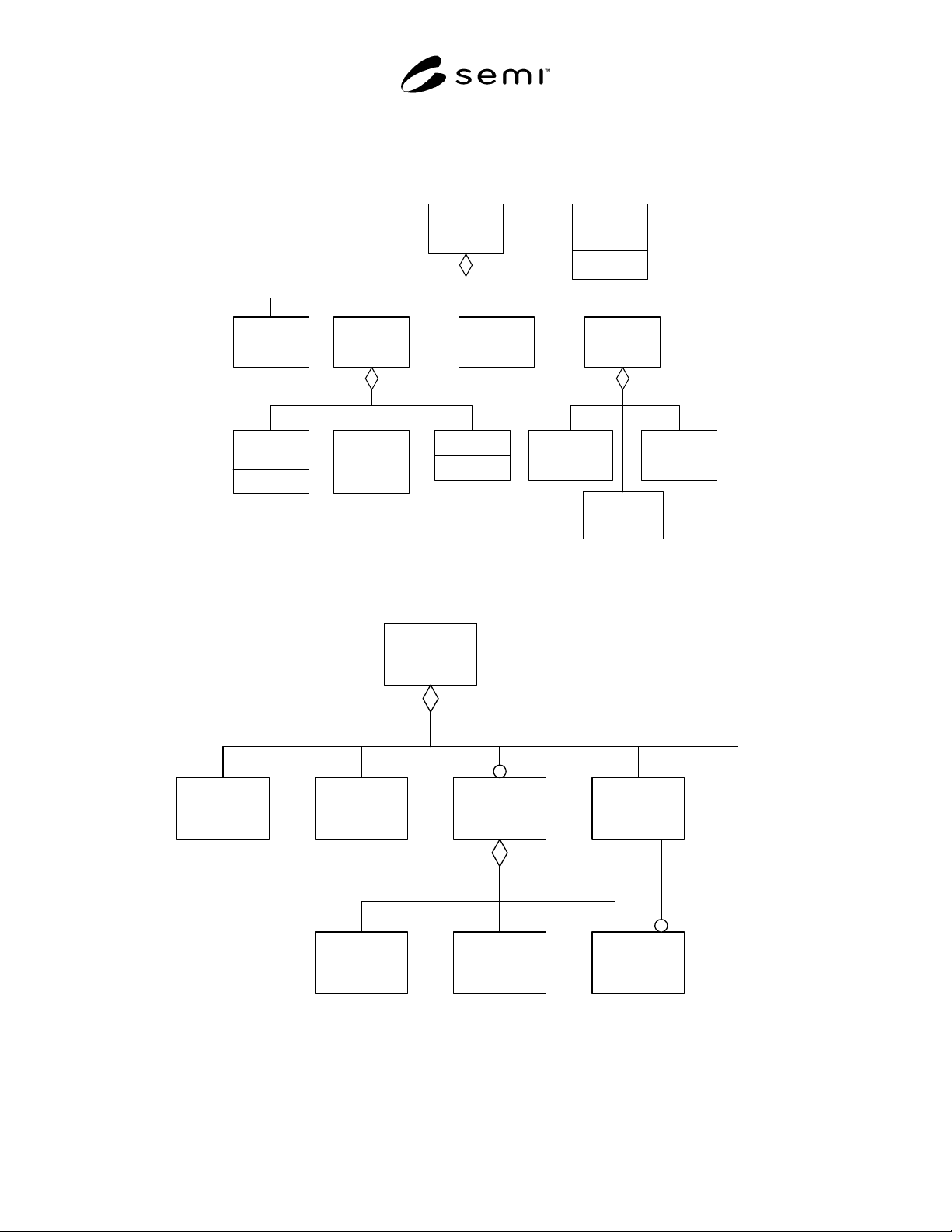
Figure R1-6
Spin/Coat Track Module Object Model
300mm
Production
Equipment
Equipment
Subsystem
(Buffer)
Equipment
Module
(Process)
Equipment
Subsystem
(LoadPort)
1+
Equipment
Subsystem
(Wafer
Transport)
...
1+1+
Equipment
Subsystem
(Carrier
Storage Unit)
Equipment
Subsystem
(Substrate
Port)
1+1+ 1+
Equipment
Subsystem
(Carrier
Transport)
Figure R1-7
Example of Object Model for 300 mm Equipment
SEMI E98-1102 © SEMI 2000, 2002 45
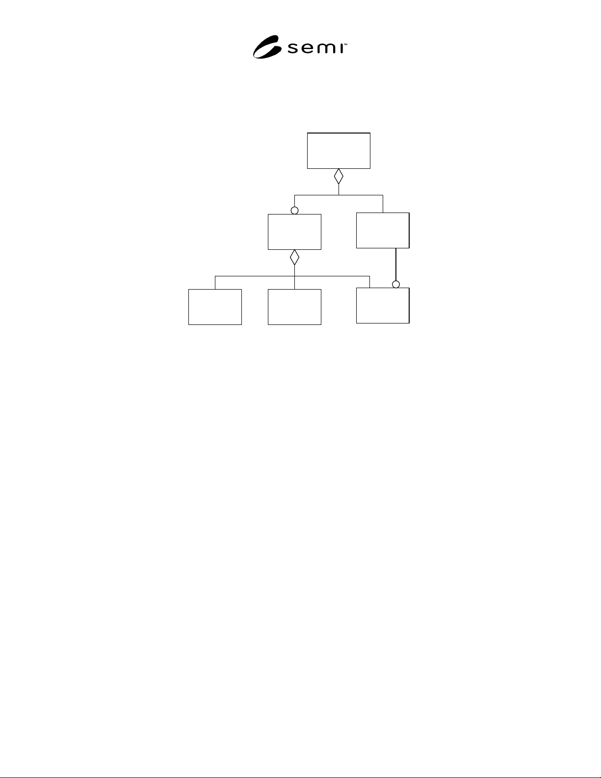
R1-2.3 The term “Equipment Front End Module” (EFEM) refers to the aggregation shown in Figure R1-8
consisting of all the components handling carriers, i.e., the loadport and buffer subsystems. An EFEM would not
typically provide ARAMS capability and therefore would be considered as an EquipmentSubsystem and not
considered as an OBEM EquipmentModule.
Equipment
Front End Module
(EFEM)
Equipment
Subsystem
(Buffer)
Equipment
Subsystem
(LoadPort)
1+
Equipment
Subsystem
(Carrier
Storage Unit)
Equipment
Subsystem
(Substrate
Port)
1+1+
1+
Equipment
Subsystem
(Carrier
Transport)
Figure R1-8
Equipment Front End Module (EFEM)

SEMI E98-1102 © SEMI 2000, 2002 46
RELATED INFORMATION 2
RELATIONSHIP TO THE CIM FRAMEWORK
NOTE: This related information is not an official part of SEMI E98. This is Related Information for the provisional specification
and is not intended to modify or supersede the official standard. Determination of the suitability of the material is solely the
responsibility of the user.
This section discusses the relationship of OBEM and
the OBEM objects to the objects defined in SEMI E81.
It uses terms both from the CIM Framework and from
OBEM. It is not part of the OBEM standard.
Additional documentation should be provided in this
section as the CIM Framework develops.
R2-1 Equipment and Machine
R2-1.1 The interface to Equipment defined in OBEM
is provided for the physical equipment on the
manufacturing floor. From time to time, the Equipment
will be powered off for maintenance and at these times
is unable to communicate. In contrast, the Machine
object, defined in the CIM Framework, is part of the
manufacturing execution system and is always
available, even when the Equipment is powered off or
otherwise unable to communicate.
R2-1.2 The Machine provides a generic interface for
factory logistics and is able to provide some services
without relying on the Equipment itself. The Machine
is responsible for communications with the Equipment
and for representing the Equipment to the Factory and
representing the Factory to the Equipment.
R2-2 EquipmentModule and MachineResource
R2-2.1 The EquipmentModule defined in OBEM
corresponds to the MachineResource interface defined
in the CIM Framework. The MachineResource is a type
of Resource and therefore can respond to requests to
start up and shut down. These services are provided for
the EquipmentModule but not for its supertypes.
R2-3 Location Tracking
R2-3.1 The CIM Framework defines an interface for a
MaterialTrackingLocation. The MaterialTracking-
Location differs from the OBEM MaterialLocation.
MaterialLocations represent places within the
equipment itself where carriers and substrates can be
placed, including wafer chucks, carrier slots, and robot
end effectors. A MaterialTrackingLocation, in contrast,
is at a higher level of granularity and provides the
ability to locate material associated with a Machine.
MaterialTrackingLocation does not track material
locations down to the level of specific places within the
equipment.