semi合集-English.pdf - 第4703页
SEMI C3.58-0303 © SEMI 2000, 2003 3 5.1.4.6.1 Calculate the sampl e’s free acidity using t he following equation: ppb HCl = (C2-C 1) × F W Where: ppb HCl = free acidity C1 = blank conductivity, µ mho/cm C2 = sample condu…

SEMI C3.58-0303 © SEMI 2000, 2003 2
5.1.4.2 Conductivity bridge/cell — Store the
conductivity cell in a polyethylene beaker containing
de-ionized water when not in use.
5.1.4.3 Calibration
5.1.4.3.1 Add CFC-11 to the 20 mL calibration mark of
the polyethylene (PE) bottle. Immediately cap the
bottle and shake contents vigorously for approximately
30 seconds. Discard the CFC-11.
5.1.4.3.2 Fill the bottle again with CFC-11 to the 20
mL mark. Immediately add 100 mL of de-ionized (DI)
water to the bottle, cap and shake vigorously for
approximately 120 seconds.
5.1.4.3.3 Rinse the conductivity cell with DI water and
shake it dry. Uncap the PE bottle and dip the
conductivity cell into the water layer (top layer). Read
and record the conductivity value. This reading will
serve as the “BLANK” value. Remove the conductivity
cell from the solution, rinse with DI water and store in a
beaker containing DI water. Immediately cap the PE
bottle.
5.1.4.3.4 Fill and flush a clean, dry, 50 microliter
syringe several times with the 0.01 N standard,
hydrochloric acid in SDA-2B ethanol. Fill the syringe
to a volume of 30 microliters. Holding the syringe
vertically with needle pointing up, tap the barrel gently
to permit air bubbles to rise to the top. Slowly depress
the plunger until the plunger tip is aligned exactly with
the 20 microliter mark. Immediately uncap the PE
bottle and inject the syringe contents into the bottle.
Immediately cap the bottle. Shake the bottle vigorously
for approximately 120 seconds. Uncap the PE bottle
and dip the conductivity cell into the water layer. Read
and record the conductivity value. Remove the
conductivity cell from the solution, rinse with DI water
and store in a beaker containing DI water.
5.1.4.3.5 Calculate the nanograms (ng) of hydrochloric
acid used in the standard from the following equation:
ng HCl = V × N × MEQ × 10
9
10
3
Where: ng HCl = nanograms of HCl in
the standard
V = HCl volume, microliters
N = HCl normality
MEQ = HCl milliequivalent weight
(g/meq) = 0.036461
5.1.4.3.6 Calculate the calibration factor as follows:
ng HCl/µmho = A
(C2-C1)
Where: ng HCl/µmho = calibration
factor
A = ng HCl in standard
C1 = blank conductivity, µmho
C2 = standard conductivity, µmho
5.1.4.3.7 Repeat procedure at least six times. Use the
average of the six calibration factors for sample
calculations.
5.1.4.4 Samplying and Analysis
5.1.4.4.1 Add CFC-11 or a similar degreasing solvent
to the 20 mL calibration mark of the polyethylene (PE)
bottle. Immediately cap the bottle and shake contents
vigorously for approximately 30 seconds. Discard the
CFC-11.
5.1.4.4.2 Fill the bottle again with CFC-11 to the 20
mL mark. Immediately add 100 mL of DI water to the
bottle, cap and shake vigorously for approximately 120
seconds.
5.1.4.4.3 Rinse the conductivity cell with DI water and
shake it dry. Uncap the PE bottle and dip the
conductivity cell into the water layer (top layer). Read
and record the conductivity value. This reading will
serve as the “BLANK” value. Remove the conductivity
cell from the solution, rinse with DI water and store in a
beaker containing DI water. Immediately cap the PE
bottle.
5.1.4.5 Weigh the sample cylinder and record. Attach
PE gas dispersion tube to the sample cylinder valve.
Uncap the PE bottle and lower the gas dispersion tube
into the water. Open the cylinder valve and purge
sample through the bottle such that about 150 g of
sample are added to the bottle over a 60 minute period.
Close the cylinder valve and immediately remove the
gas dispersion tube and cap the bottle. Record the final
weight of the capped sample cylinder.
5.1.4.6 Shake the PE bottle vigorously for
approximately 120 seconds. Read and record the
conductivity value as done previously.

SEMI C3.58-0303 © SEMI 2000, 2003 3
5.1.4.6.1 Calculate the sample’s free acidity using the
following equation:
ppb HCl = (C2-C1) × F
W
Where: ppb HCl = free acidity
C1 = blank conductivity, µmho/cm
C2 = sample conductivity, µmho/cm
F = calibration factor, ng HCl/µmho
W = sample weight used in analysis,
grams
6 Analytical Procedures - Instrumental
Analysis
6.1 Air (N
2
,O
2
, CO, CO
2
) and Oxygen — This
procedure is for the determination of air components in
octafluorocyclobutane using a gas chromatograph with
a discharge ionization detector. Column switching is
used to separate and elute the components and to
backflush octafluorocyclobutane. One method/column
is used for N
2
, O
2
, and CO and a second
method/column is used for CO
2
. The sample should be
taken from the vapor in the container directly into the
instrument sampling system. The container being
analyzed should have equilibrated at approximately
30°C before analysis is begun.
6.1.1 Detection Limits — Nitrogen, 10 ppb vol;
Oxygen, 50 ppb vol; Carbon monoxide, 10 ppb vol;
Carbon dioxide, 10 ppb vol.
6.1.2 Instrument Parameters
6.1.2.1 Columns: Precolumn: Haysep DB on
Carbopack B, 80/100 mesh, 2 ft × 1/8 in stainless steel.
N
2
, O
2
, CO column: Molecular Sieve 5a, 80/100 mesh,
8 ft × 1/8 in stainless steel. CO
2
column: Haysep DB
on Carbopack B, 80/100 mesh, 8 ft × 1/8 in stainless
steel.
6.1.2.2 Gas Flows: Helium carrier gas 40 mL/min for
each column.
6.1.2.3 Sample volume: 1.0 mL
6.1.2.4 Temperatures: Detector setpoint = 25°C
(actual is higher ~60°C due to proximity to the oven),
Oven 77°C isothermal.
6.1.2.5 Calibration Standard: 1-30 ppm vol oxygen,
nitrogen, carbon monoxide, and carbon dioxide in
helium.
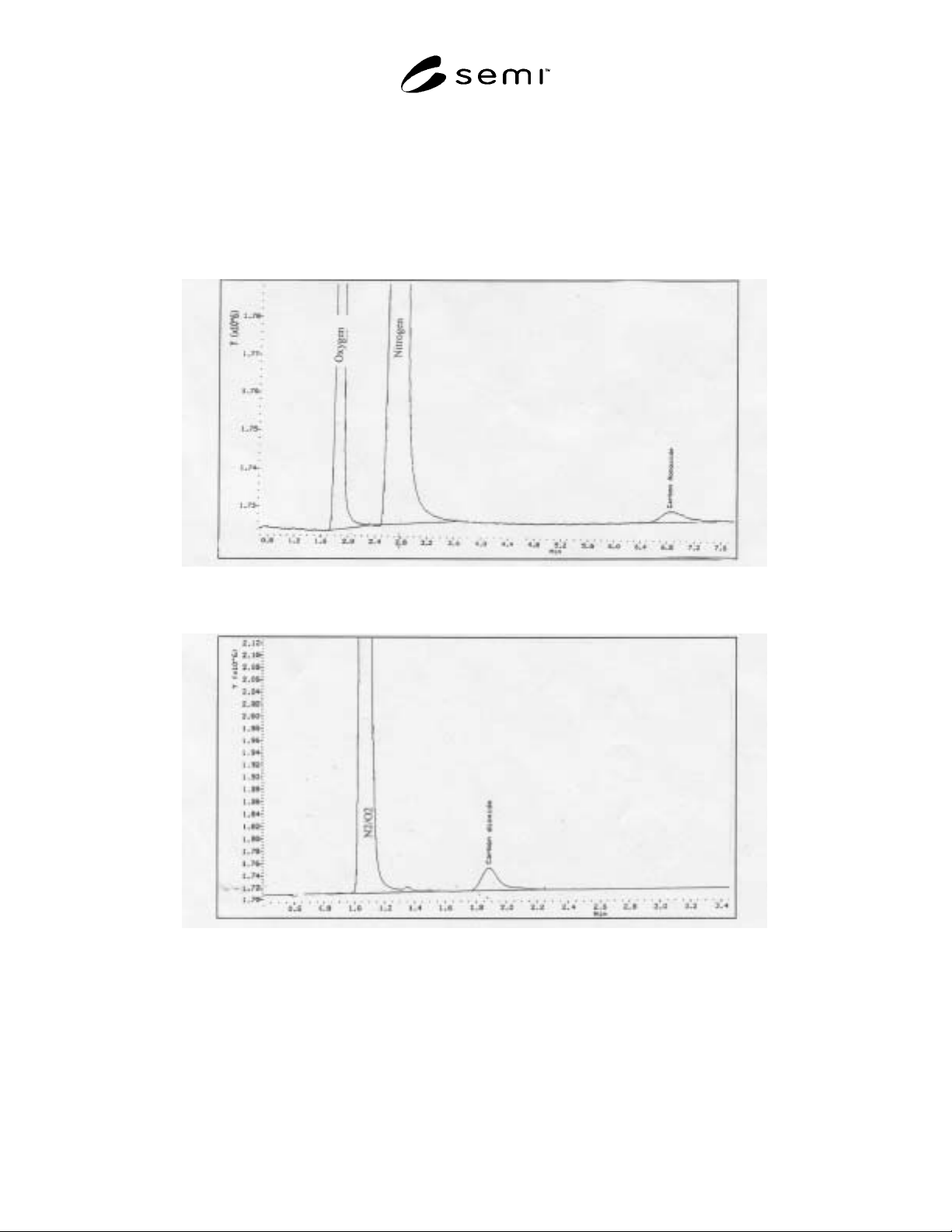
6.1.2.6 Chromatograms — See Figures 1,2.
6.2 Organic Impurities — This procedure is for the
determination of organic impurities in
octafluorocyclobutane using a gas chromatograph with
a packed column and flame ionization detector.
6.2.1 Detection Limits
PFC-1216 (hexafluoropropene),
PFC-31-10mc (n-decafluorobutane),
PFC-1318my (octafluorobutene, cis and trans)
0.1 vol, ppm
PFC-31-10my (iso-decafluorobutane),
CFC-114 (1,2-dichloro-1,1,2,2-tetrafluoroethane),
CFC-114a(1,1-dichloro-1,2,2,2-tetrafluoroethane),
THF(tetrahydrofuran)
0.2 vol, ppm
6.2.2 Instrument Parameters
6.2.2.1 Column — 1% SP-1000, on Carbopack B,
60/80 mesh, 24 ft × 1/8 in stainless steel or equivalent.
6.2.2.2 Gas Flows — Helium carrier gas, 20
mL/minute.
6.2.2.3 Sample volume — 1.0 mL vapor.
6.2.2.4 Temperatures — Injector = 150°C, Detector =
250°C, Oven: 75°C for 10 minute, increase 8°C/min to
200°C and hold for 10 minutes.
6.2.2.5 Calibration Standard: 1-50 ppm vol, PFC-
1216, PFC-31-10my, PFC-31-10mc, PFC-1318my (cis
and trans), CFC-114/114a, and THF in
octafluorocyclobutane.
6.2.2.6 Chromatogram — See Figure 3.
6.3 Water — This procedure is for the determination of
trace moisture (water) in Octafluorocyclobutane, using
oscillating crystal technology. The instrument monitors
the change in vibrational frequency of a
hygroscopically sensitized quartz crystal when it is
exposed alternately to wet and dry sample gas. The
change in vibrational frequency is a function of the
amount of moisture sorbed from the wet sample gas.
The sample should be taken from the vapor in the
container directly into the instrument sampling system.
The container being analyzed should have equilibrated
at approximately 30°C before analysis is begun.
6.3.1 Detection Limit — 0.04 ppm vol (40 ppb vol).
6.3.2 Sample Pressure and Flow — These parameters
should be set in accordance with instrument
manufacturer’s instructions.
SEMI C3.58-0303 © SEMI 2000, 2003 4
6.3.3 Operation Check — The instrument should be checked periodically for correct operation. The instrument
should be zeroed by flowing reference gas, which is dry octafluorocyclobutane (dried by use of an ultra dryer system
provided by the instrument manufacturer). Then the instrument should be calibrated by use of the internal moisture
generator (permeation tube) which has been certified by the manufacturer at some known moisture level. When not
in use the instrument should be purged with dry gas (i.e., helium or nitrogen).
6.3.4 Operation Procedures
6.3.4.1 Initiate flow of the reference gas to the instrument and allow 30 minutes for stabilization.
Figure 1
Nitrogen, Oxygen, and Carbon Monoxide Determination in Octafluorocyclobutane
Figure 2
Carbon Dioxide Determination in Octafluorocyclobutane