semi合集-English.pdf - 第2776页
SEMI E98-1102 © SEMI 2000, 2002 41 RELATED INFORMATION 1 MODELS NOTE: This related information is not an official part of SEMI E98. This is Rela ted Information for the provisional specificati on and is not intended to m…
SEMI E98-1102 © SEMI 2000, 2002 40
12.21 Stop — Table 34 defines the service for stopping an activity at the equipment or one of its modules.
Table 34 Stop Service Definition
Parameter Req/Ind Rsp/Conf Description
ObjSpec M - Object specifier for EquipmentModule or Equipment.
RequestStatus - M Result status
12.22 SynchDate&Time — The SynchDate&Time service instructs the equipment to synchronize date and time with
the network at its next opportunity to do so at a time where a timestamp series for work in process will not be
compromised by a change in date or time. This service is defined in Table 35.
Table 35 SynchDate&Time Service
Parameter Req/Ind Rsp/Conf Description
RequestStatus - M Result status
13 Services Provided by Factory Systems
13.1 This section describes the services provided by the factory system. These are messages sent by the equipment
to the factory system.
13.2 Date and Time Request — The equipment may request the current date and time from the factory system. This
message service is identical to the GetDateTime service defined in Section 12.6 and Table 23.
13.3 Event Notification — The factory system will receive standard event notifications from the equipment. Event
notifications used will depend upon the protocol used.
13.4 Alarm and Error Notifications — The factory system will receive notifications of errors and alarms. Errors
may be recoverable. Equipment shall comply to SEMI E41.
14 OBEM Compliance
NOTE 6: Section must be completed in order for the provisional status of OBEM to be removed.
15 Scenarios
NOTE 7: Section must be completed in order for the provisional status of OBEM to be removed.
15.1 This section contains scenarios showing typical interactions between factory and equipment, including
interactions defined by other standards.
NOTICE: SEMI makes no warranties or representations as to the suitability of the provisional standards set forth
herein for any particular application. The determination of the suitability of the provisional standard is solely the
responsibility of the user. Users are cautioned to refer to manufacturer’s instructions, product labels, product data
sheets, and other relevant literature respecting any materials mentioned herein. These provisional standards are
subject to change without notice.
The user’s attention is called to the possibility that compliance with this provisional standard may require use of
copyrighted material or of an invention covered by patent rights. By publication of this provisional standard, SEMI
takes no position respecting the validity of any patent rights or copyrights asserted in connection with any item
mentioned in this provisional standard. Users of this provisional standard are expressly advised that determination of
any such patent rights or copyrights, and the risk of infringement of such rights, are entirely their own responsibility.
SEMI E98-1102 © SEMI 2000, 2002 41
RELATED INFORMATION 1
MODELS
NOTE: This related information is not an official part of SEMI E98. This is Related Information for the provisional specification
and is not intended to modify or supersede the official standard. Determination of the suitability of the material is solely the
responsibility of the user.
This section provides examples of equipment models to clarify the standard.
R1-1 Linked Litho Model
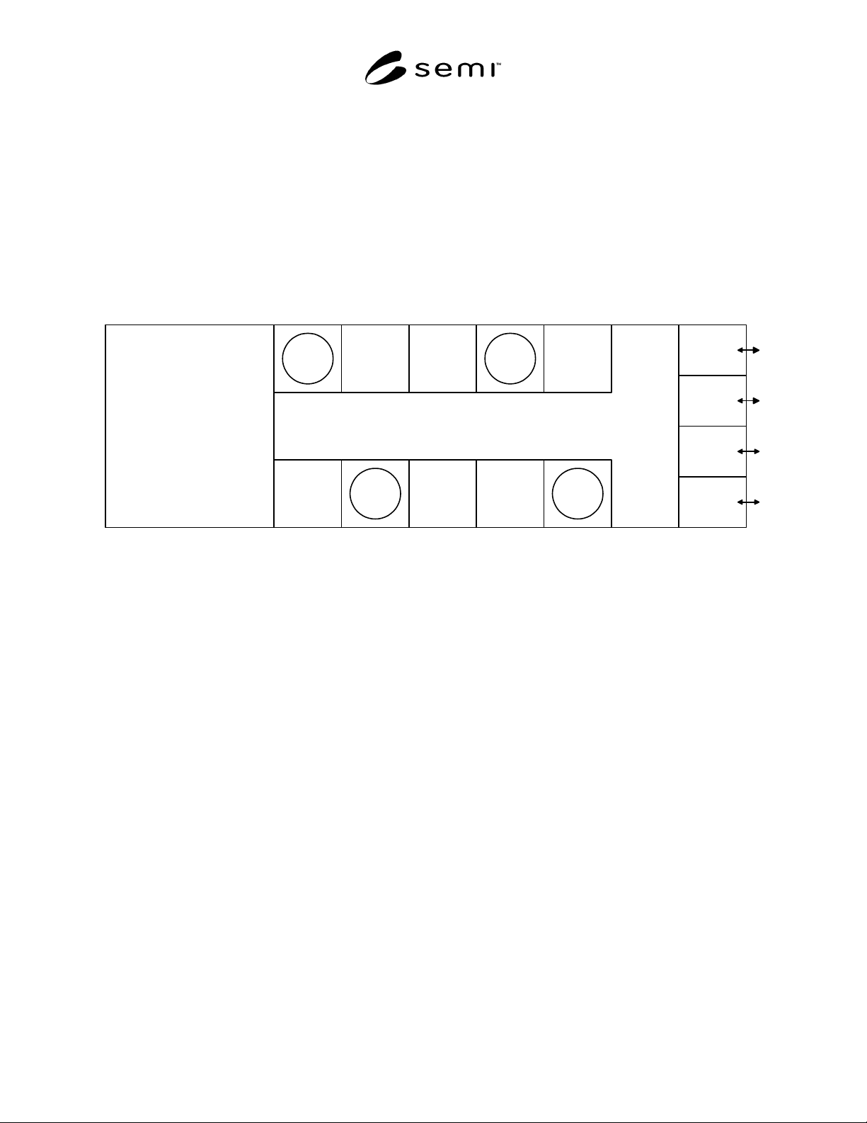
R1-1.1 This section describes the application of OBEM objects to a linked litho as illustrated in Figure R1-1.
Expose
Chill
Plate
Vacuum
Bake
Coat
Chill
Plate
Vapor
Prime
Post-
Expose
Bake
Chill
Plate
Develop Bake
Chill
Plate
Chill
Plate
Load
Port
Load
Port
Chill
Plate
Chill
Plate
Chill
Plate
Load
Port
Load
Port
Figure R1-1
Illustration of Linked Litho
R1-1.2 A linked litho is an aggregate created by physically connecting an apply/develop track to a lithography
equipment. Work enters through the track where it goes through a set of initial processing steps. Individual
substrates are passed to the lithography equipment where they are exposed and returned to another part of the track,
where they complete another set of processing steps. Both the track and the lithography equipment are capable of
acting independently. However, in the linked-litho configuration, they must perform together as a single system and
are treated as a single Equipment by the factory.
R1-1.3 Apply/Develop Track Equipment
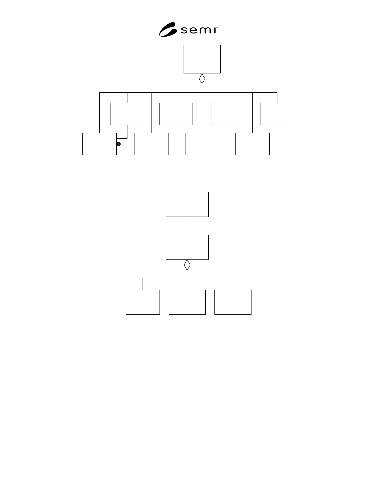
R1-1.3.1 Before considering the object model for a linked litho, it is helpful to examine the model for an
apply/develop track as a type of stand-alone equipment. This is illustrated in Figure R1-2.
SEMI E98-1102 © SEMI 2000, 2002 42
Equipment
Module
(Apply &
Develop
Track)
Equipment
Subsystem
(LoadPort)
Equipment
Subsystem
(Wafer
Transport)
Equipment
Module
(Chill Plate)
Equipment
Module
(Vapor
Prime)
1+
Equipment
Module
(Vacuum
Bake)
Equipment
Module
(Apply)
Equipment
Module
(Develop)
1+
1+
1+
1+ 1+ 1+
Equipment
Subsystem
(Temp
Control)
used by
used by
1+
Figure R1-2
Apply and Develop Track Equipment
Equipment
(Linked
Litho)
Equipment
Module
(Expose)
User
Equipment
Subsystem
(Load Port)
2+
Equipment
Module
(Track)
2+
1+
Figure R1-3
Object Model for Linked Litho Equipment