semi合集-English.pdf - 第4410页
SEMI F97-0305 © SEMI 2005 20 RELATED INFORMATION 1 APPLICATION EXAMPLES NOTICE : This rel ated information is not an o fficial part of SEMI F97 a nd was derive d from work of the origi nating task force. This related inf…

SEMI F97-0305 © SEMI 2005 19
11.2.2.3 Post Conditions:
Post condition 1..n: The FPU shall reflect the new value of the variable set by the Set Data.
11.2.2.4 It is recommended that all parameters supported by Set Data are tested.
11.2.3 Get Data Test (if supported by FPU)
11.2.3.1 Preconditions:
FMCS and FPU are connected.
FMCS is ready to issue a Get Data.
11.2.3.2 Test Operations:
Operation 1..n: A test person shall set the variable at the FPU to a particular value. The FMCS shall issue a Get
Data against the FPU.
11.2.3.3 Post Conditions:
Post condition 1..n: The FMCS shall visualize the new value of the variable.
11.2.3.4 It is recommended that all parameters supported by Get Data are tested.
11.3 Compliance
11.3.1 Table 15 provides a checklist for compliance with this standard.
Table 15 Compliance Checklist
Section Implemented Compliant
Fundamental Requirements
Watchdog-Toggle 9.4.2 Yes No Yes No
OP-Mode 9.4.3 Yes No Yes No
Run-Mode 9.4.5 Yes No Yes No
Error-Mode 9.4.8 Yes No Yes No
Get Status Operation 9.5.2 Yes No Yes No
Optional Capabilities
Control-Mode 9.4.4 Yes No Yes No
Alarm-Mode 9.4.6 Yes No Yes No
Warning-Mode 9.4.7 Yes No Yes No
Maintenance-Mode 9.4.9 Yes No Yes No
Simulation Mode 9.4.10 Yes No Yes No
Lock-Mode 9.4.5.2 Yes No Yes No
Set Data Operation 9.5.3 Yes No Yes No
Get Data Operation 9.5.4 Yes No Yes No
SEMI F97-0305 © SEMI 2005 20
RELATED INFORMATION 1
APPLICATION EXAMPLES
NOTICE: This related information is not an official part of SEMI F97 and was derived from work of the originating
task force. This related information was approved for publication by full letter ballot on November 10, 2004.
R1-1 Application Examples
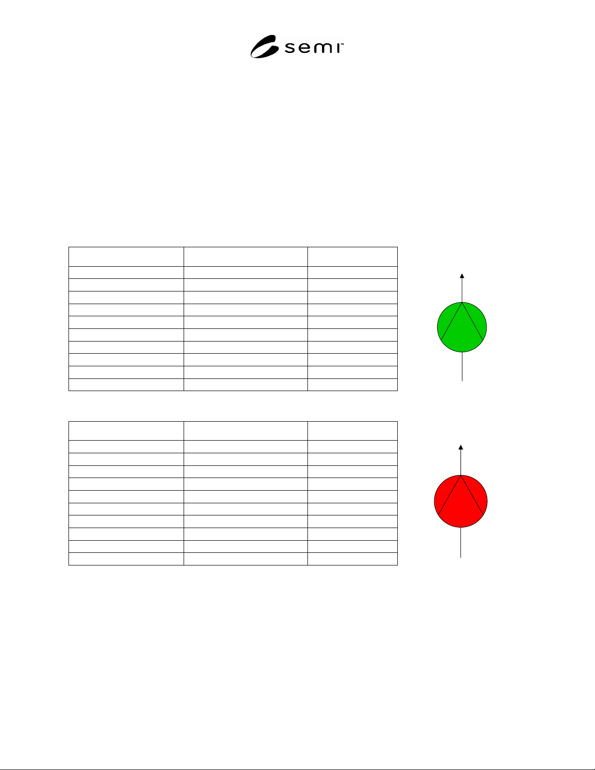
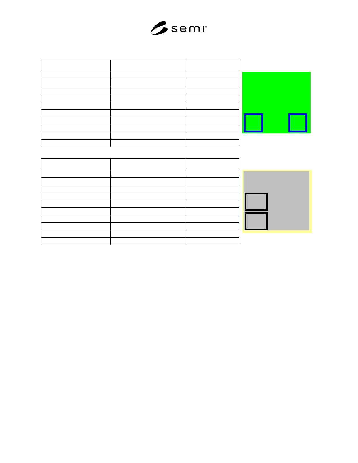
R1-1.1 In order to help with understanding of FPU states specified in this standard, this Related Information
provides examples of their use. Examples of simple and more complex FPUs are given. The status of the FPU
retrieved by the FMCS is depicted in a table. In addition, a picture is given that might visualize the FPU status by
the FMCS.
R1-2 Simple FPU – Pump
Table R1-1 Status Response of a Pump in Operation
Status Field Name Meaning Value FMCS- Visualization
Watchdog-Toggle Toggle value (not supported) 0
OP-Mode Automatic 1
Control-Mode Local 0
Run-Mode Run 3
Alarm-Mode No_Alarm 0
Warning-Mode No_Warning 0
Error-Mode No_Error 0
Maintenance-Mode No_Maintenance 0
Simulation-Mode No_Simulation 0
Lock-Mode Not_Locked 0
Table R1-2 Status Response of a Pump That is Not Operating Because of an Alarm, e.g. Motor-Overheat
Status Field Name Meaning Value FMCS- Visualization
Watchdog-Toggle Toggle value (not supported) 0
OP-Mode Automatic 1
Control-Mode Local 0
Run-Mode Down (unscheduled) 0
Alarm-Mode Alarm 1
Warning-Mode No_Warning 0
Error-Mode No_Error 0
Maintenance-Mode No_Maintenance 0
Simulation-Mode No_Simulation 0
Lock Not_Locked 0
SEMI F97-0305 © SEMI 2005 21
R1-2 Complex FPU – Makeup Air Unit (MAU)
Table R1-3 Status Response of a MAU in Run, Locked and Automatic Mode
Status Field Name Meaning Bit-value
Watchdog-Toggle Toggle value 0/1
OP-Mode Automatic 1
Control-Mode Remote 1
Run-Mode Run 3
Alarm-Mode Alarm 0
Warning-Mode No_Warning 0
Error-Mode No_Error 0
Maintenance-Mode No_Maintenance 0
Simulation-Mode No_Simulation 0
Lock Locked 1
Makeup Air Unit
MAU007
L
A
Table R1-4 Status Response of a MAU in Maintenance Mode
Status Field Name Meaning Bit-value
Watchdog-Toggle Toggle value 0/1
OP-Mode Automatic 1
Control-Mode Local 0
Run-Mode Stand-by 2
Alarm-Mode Alarm 0
Warning-Mode No_Warning 0
Error-Mode No_Error 0
Maintenance-Mode Maintenance 1
Simulation-Mode No_Simulation 0
Lock Not_Locked 0
Makeup Air Unit
MAU007
M
L