semi合集-English.pdf - 第504页
SEMI E73-0301 © SEMI 1998 , 2001 1 SEMI E73-0301 SPECIFIC A TI ON FOR VACUUM PUMP INTERFACES - DRY PU M PS This specific ation was techn ically appr oved by the Glob al Physical Interfaces & Carri ers Committee an d …

SEMI E72-0600 © SEMI 1998, 2005 5
RELATED INFORMATION 1
APPLICATION NOTES
NOTICE: This related information is not an official part of SEMI E72 but was approved for publication by full letter
ballot procedures.
R1-1 The maximum height of equipment in the main fab was set so that the equipment could be installed in
existing fabs with ceilings just above the equipment height of 3.5 m (11 ft. 5 in) or in fabs with ceiling heights of
3.66 m (12 ft. 0 in.) where more clearance is provided for such things as parts of some overhead carrier transport
systems, fire sprinkler systems at the ceiling, and/or extra room for installation of equipment.
R1-2 The maximum height of equipment in the sub-fab was set so that no part of the equipment (other than
connections to the main fab area) sticks up into the piping and duct-work immediately under the waffle slab. In
those cases where a part of the equipment must be taller than 2 m (6 ft. 6 in.), it is recommended that it not be taller
than 2.5 m (8 ft. 2 in.) to stay under the waffle slab.
R1-3 If equipment must have easement space on the side, it is recommended that they be designed in mirror-image
configurations with easement space needed on only one side or the other, so that half of the total easement space on
the sides can be deleted. However, it is recommended that the resulting increase in equipment cost, complexity, and
spare parts inventory be taken into account.
R1-4 Equipment that conforms to the limits given in this standard may be too large or heavy to fit into buildings
that were originally designed for equipment that processes smaller wafers.
NOTICE: SEMI makes no warranties or representations as to the suitability of the standards set forth herein for any
particular application. The determination of the suitability of the standard is solely the responsibility of the user.
Users are cautioned to refer to manufacturer's instructions, product labels, product data sheets, and other relevant
literature, respecting any materials or equipment mentioned herein. These standards are subject to change without
notice.
By publication of this standard, Semiconductor Equipment and Materials International (SEMI) takes no position
respecting the validity of any patent rights or copyrights asserted in connection with any items mentioned in this
standard. Users of this standard are expressly advised that determination of any such patent rights or copyrights, and
the risk of infringement of such rights are entirely their own responsibility.
Copyright by SEMI® (Semiconductor Equipment and Materials
International), 3081 Zanker Road, San Jose, CA 95134. Reproduction of
the contents in whole or in part is forbidden without express written
consent of SEMI.
SEMI E73-0301 © SEMI 1998, 20011
SEMI E73-0301
SPECIFICATION FOR VACUUM PUMP INTERFACES - DRY PUMPS
This specification was technically approved by the Global Physical Interfaces & Carriers Committee and is
the direct responsibility of the Japanese Physical Interfaces & Carriers Committee. Current edition approved
by the Japanese Regional Standards Committee on December 1, 2000. Initially available at www.semi.org
January 2001; to be published March 2001. Originally published June 1998; previously published February
1999.
1 Purpose
1.1 This standard specifies the physical and electrical
interfaces for dry pump (DRP) type vacuum pumps.
Standardization of pump interfaces will allow for
interchangeability of pumps. Device manufacturers use
this standard when procuring processing equipment to
specify to the equipment supplier the interface required
for interchangeability of pumps. This document is also
used by semiconductor processing equipment suppliers
to specify standardized interfaces to pump suppliers.
2 Scope
2.1 This standard applies to vacuu m pumps supplied
with 300 mm semiconductor processing equipment.
2.2 The standard specifies the mec hanical and
electrical interfaces for dry pumps including the
following.
• Mechanical connectors
• Control signals and connector
• Power supply and connector
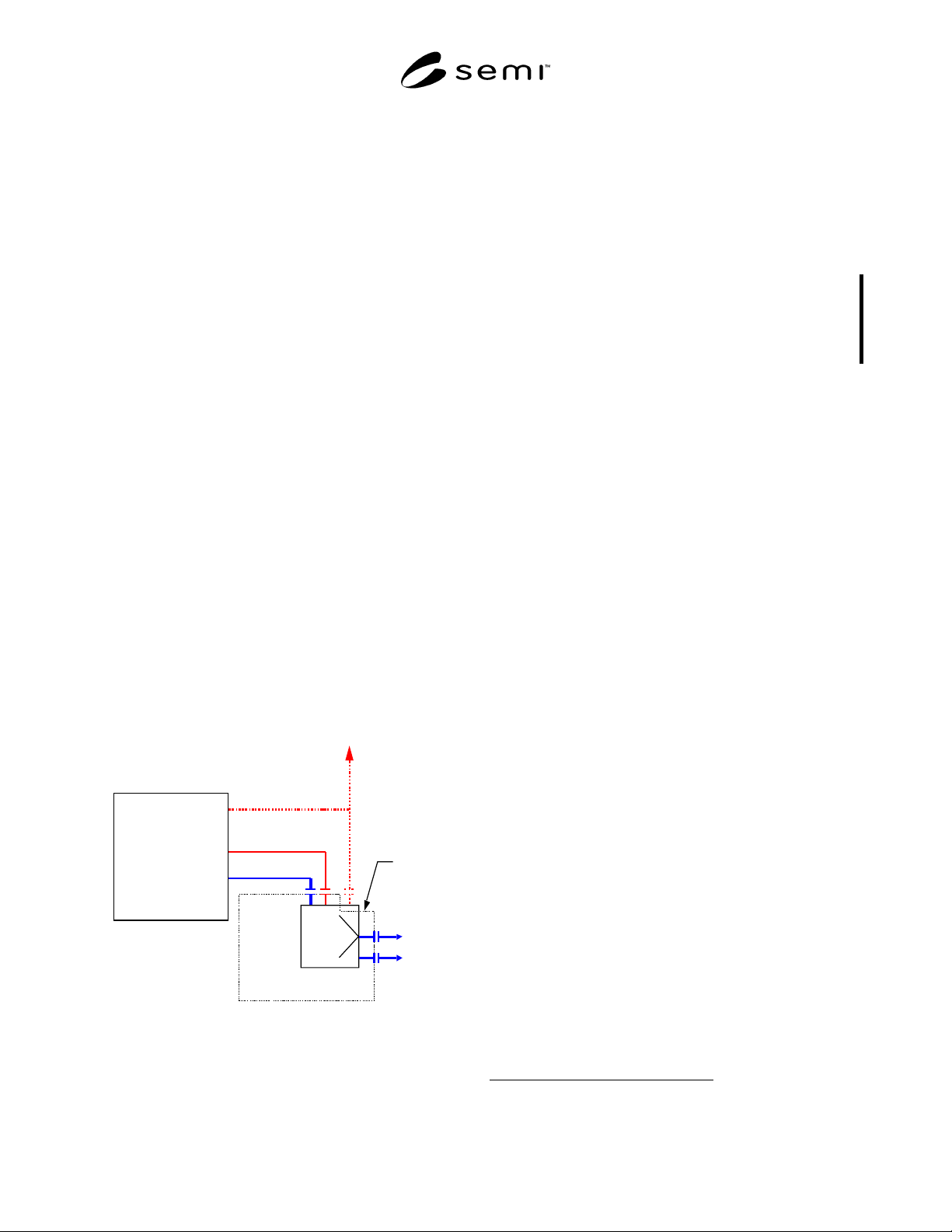
2.3 Figure 1 shows the scope of the standardized
interface.
Tool
Physical interface
Electrical interface
Signals for
centralized supervisory
Outlet
Range of
standardized
items
Utilities
Figure 1
Scope of Standardized Interface
2.4 This standard does not purport to address safety
issues, if any, associated with its use. It is the
responsibility of the users of this standard to establish
appropriate safety and health practices and determine
the applicability of regulatory limitations prior to use.
3 Limitations
3.1 This guide is not intended to d ictate how to build a
vacuum pump but to specify interfaces that will allow
for interchangeabilty of individual pumps.
3.2 This standard does not include specifications for
sensor-bus compliant interfaces.
3.3 This standard is not intended t o address design
issues related to safety considerations and containment
issues which are addressed elsewhere in the SEMI
guidelines.
3.4 International, national, and loc al codes, laws, and
regulations should be consulted to ensure that the
equipment meets regulatory requirements in each
location of use.
4 Referenced Standards
NOTE 1: As listed or revised, all documents cited shall be the
latest publications of adopted standards.
4.1 SEMI Documents
SEMI S2 — Environmental, Health, and Safety
Guideline for Semiconductor Manufacturing Equipment
4.2 ISO Documents
1
ISO 7-1 — Pipe threads where pressure-tight joints are
made on the threads - Part 1: Dimensions, tolerances
and designation
ISO 1609 — Vacuum Technology - Flange dimensions
ISO 2861-1 — Vacuum technology - Quick-release
couplings - Dimensions - Part 1: Clamped type
5 Terminology
5.1 dry pump (DRP) Dry pumps are a type of
mechanical vacuum pump. Dry pumps can work at
1 International Organization for Standardization, C.P. 56 CH-1211
Geneva 20, Switzerland
SEMI E73-0301 © SEMI 1998, 2001 2
atmospheric pressure. They are called dry pumps
because no liquid sealing materials are used on any
surface contacted by gases. Hereafter, the term “DRP”
is substituted for “dry pump”.
5.2 pump alarm A cautionary s ignal that the pump
has stopped.
5.3 pump warning A state of an abnormal or
extraordinary event during pump operation which
means there is a probability the pump will stop.
5.4 vacuum pump A pumping a pparatus which
exhausts gas or air from an enclosed space to achieve a
desired degree of vacuum.
6 Requirements
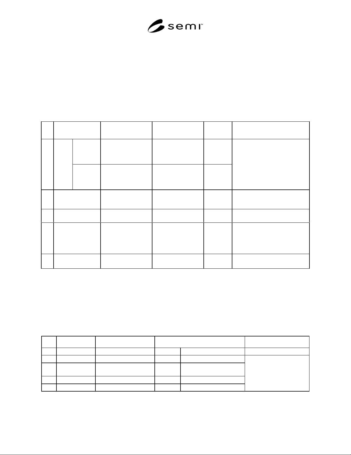
6.1 Mechanical Interfaces — Table 1 specifies the
required DRP connector type and size by flange/port.
Table 1 Mechanical Connectors
No. Items Connector Type Connector Size
Referenced
Standard
Remarks
Nominal
bore 50 mm
or less
ISO KF flange ≤ 50 mm
Connector dimensions
should be based on the
referenced standard
ISO 2861-1
1Inlet
flange
Nominal
bore over
63 mm size
ISO clamped flange ≥ 63 mm
Connector dimensions
should be based on the
referenced standard
ISO 1609
A port flange which connects the
pump to a process tool to evacuate
gases.
2 Outlet flange ISO KF flange Connector dimensions
should be based on the
referenced standard
ISO 2861-1 A port flange which connects the
pump to the facility evacuation
system.
3 Duct port (Option) Not specified 50 mm or 100 mm
diameter port
Port to connect duct for evacuating
flames inside the pump.
4 Purge gas port Compression type* 1/4" Connector A connection port used to supply
inert gas, typically N
2
, to the pump.
The purge gas protects the inside of
the pump from corrosion due to
process gases.
5 Cooling water port ISO taper pipe thread
(female on pump side)
1/4" or 3/8" ISO 7-1 A connection port to supply water
used to keep the pump cool.
* For example Swagelock
®
6.2 Electrical Interfaces
6.2.1 Control Signals
6.2.1.1 Table 2 specifies the required DRP control signals. Table 3 and Figure 2 specify the required response time
for DRP control signals. Table 4 specifies the required power and contacts for DPR control signals. Tables 5 and 6
and Figure 3 specify the required connector and pin assignments for DRP control signals.
Table 2 I/O Signals
No. Signal Name Direction Type Remarks
1 Start (Run)/Stop Input signal to Pump Alternate Pump runs when closed
2 Start (Run)/Stop Output signal from Pump Alternate Close on pump start
3 Remote/Local Output signal from Pump Alternate Close during remote
operation
4 Pump Warning Output signal from Pump Alternate Open at warning
5 Pump Alarm Output signal from Pump Alternate Open at alarm
Running status signals
When input power is OFF,
output status signals should
become open (normally
open).