semi合集-English.pdf - 第1487页
SEMI E30.5-0302 © SEMI 2001, 2002 15 10 Alarm List 10.1 Since eac h model of equip ment diff ers in configuration, it is not p ractical to pr ovide an exhaustive list of all possible alarms. Instead, the MSEM is requ iri…
SEMI E30.5-0302 © SEMI 2001, 2002 14
Variable name Category Description Class Format Comments
SlotID CV The cassette slot number. DVVAL
U4
WaferID CSV Physical wafer identifier. SV
A[1..24]
WaferIDRead CSV Tool read wafer identifier. SV
A[1..24]
WaferSize CV The nominal diameter of a silicon
wafer.
EC
A[1..16]
mm
XlateData CSV Variable for the equipment to
report the pattern-based
coordinate system offset from the
wafer-based coordinate system
found on the wafer being tested.
SV
L,4
1 <DeltaX>
2 <DeltaY>
3 <Theta>
4 <ScaleFactor>
See Appendix 1
for an example.
See Table 5 for
additional
information.
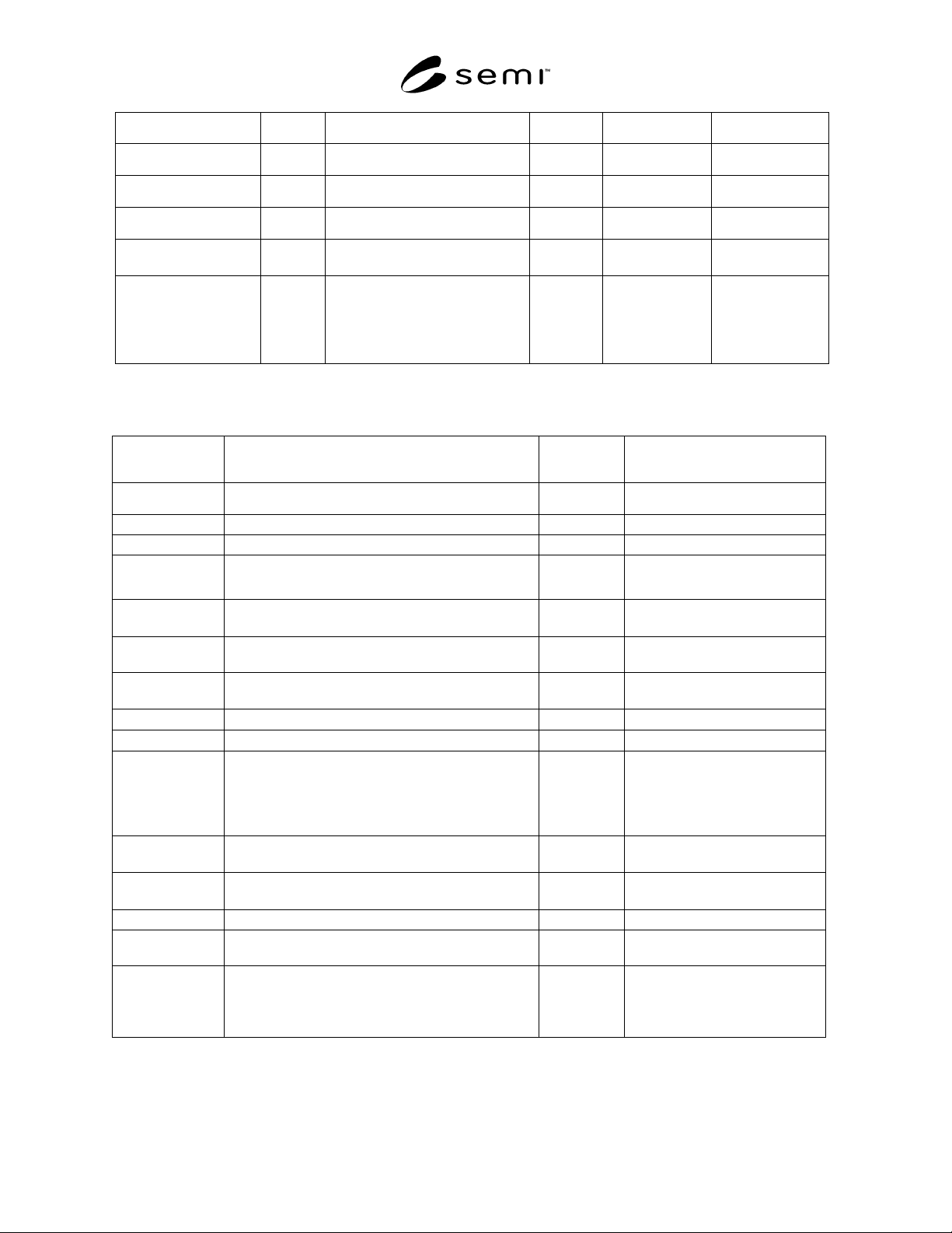
9.6.5 Data Item Sub-variable List
Table 5 Data Item Sub-Variable List
Data Item Sub-
variables
Description Format Comment
AlignName The identifier given to a alignment site. A[1..16]
CoordX The x coordinate for a site. F4 Units are in microns.
CoordY The y coordinate for a site. F4 Units are in microns.
DeltaX The x axis translation between the origins of two
coordinate systems, in µm.
F4 Units are in microns.
DeltaY The y axis translation between the origins of two
coordinate systems, in µm.
F4 Units are in microns.
ElementID The M21 address for a specific rectangular element
on a patterned silicon wafer.
I4[2] M21 row number, M21 column
number
Fiducial The type of primary fiducial on a silicon wafer. A[1..16] Options are “FLAT” or
“NOTCH”
M21XSize
The M21 element size in the x direction, in µm.
F4 Units are in microns.
M21YSize
The M21 element size in the y direction, in µm.
F4 Units are in microns.
ScaleFactor The scaling factor required by the equipment to
adjust from its SEMI M20 coordinate system to the
coordinate system established through the use of
pattern alignment “alignment site” information. In
most cases, a scaling factor of 1 is expected.
F4
SiteDeltaX The x axis translation between the defined and
found locations of a site, in µm.
F4 Units are in microns.
SiteDeltaY The y axis translation between the defined and
found locations of a site, in µm.
F4 Units are in microns.
SiteName A unique identifier for a site. A[1..16]
THETA (Θ)
The clockwise rotation, in radians, between the
SEMI M20 and M20P coordinate system axes.
F4 Radians
Tile A flag to indicate whether the SEMI M21 layout is
tiled, and in which direction.
A[1..16] Options are:
“NTILE” is untitled “CTILE”
is column tiled “RTILE” is
row tiled

SEMI E30.5-0302 © SEMI 2001, 200215
10 Alarm List
10.1 Since each model of equipment differs in
configuration, it is not practical to provide an
exhaustive list of all possible alarms. Instead, the
MSEM is requiring the two tables provided as
described in SEMI E30 (Document Section). Alarm
List Table which is intended to provide for equipment
configuration specific alarms and Alarm ID, Alarm
Set/Cleared Event Table.
10.2 Alarm List Table
10.2.1 The alarm list table contains examples of alarms
that pertain to various configurational aspects of
equipment. These examples are intended to illustrate
that alarms pertain to situations in which there exists a
potential for exceeding physical safety limits associated
with people, equipment, and material being processed
as per the SEMI E30 definition of an alarm. See SEMI
E30 for further reference.
10.3 Alarm ID, Alarm Set/Cleared Event Table
10.3.1 The Alarm ID, Alarm Set/Cleared Event table
documents the association of each ALID to a set and
cleared event as required by SEMI E30. See SEMI E30
for further reference.
11 Process Program Management
11.1 Requirements
The MSEM requires that the
SEMI E30 capability of Process Program Management
be fully supported for this class of equipment. The
MSEM is also requiring that the Process Program have
a structure that enables the user to build Process
Programs with default conditions that can be overridden
for a run. MSEM is requiring the ability to vary; the
quantity of substrates measured, the alignment
information used and the number and/or location of the
sites to be measured through the uses of Process
Program variable parameters. The concepts of Process
Program Structure and Process Program variable
parameters are discussed in the following sections.
11.2 Process Program Structure
11.2.1 Definition and Rules for Process Programs
A Process Program contains information and/or
instructions required for the metrology equipment to
process a given run of material. Equipment constants
can be used to supplement the information contained in
a Process Program.
11.2.1.1 The Process Program shall supply all of the
information required for a remotely executed run to be
processed without operator intervention. Any
information that is normally requested from the
operator console in manual operation shall have default
values assigned in the body of the Process Program.
11.2.1.2 Process-program parameters are used to tailor
a specific run of material and do not permanently
modify the Process Program. They will remain in
effect only until the next run or until the next PP-
UPDATE or PP-SELECT, PP-ASSIGN remote
command.
11.2.1.3 MSEM is requiring the ability to define
specific Process Program variable parameters to; define
what substrates are to be measured (Process SlotList),
what sites are to be measured (SiteList or M21SiteList)
and what aligns are used by the Process Program
(AlignList or M21AlignList). If the MSEM equipment
is using the SEMI M21 coordinate system then an
additional Process Program variable parameter is
required what elements are to be measured
(ElementList).
11.2.2 Definition of Process Program Variable
Parameters
A process-program parameter specifies
a value that temporarily modifies the value of a variable
parameter in a Process Program. A variable parameter
is formally defined within a process-program body and
contains:
• a variable parameter name that is unique in the
body
• a parameter initial value, known as default value,
for use when the Process Program is selected for
execution without specification of an override
value for this variable parameter.
11.2.3 The Equipment may also support the definition
including:
• a parameter restriction that represents one or more
conditions that any value specified for the
parameter must satisfy.
• a CP-NAME in a remote command must be
identical to a variable parameter name in the
Process Program specified in the remote command.
If the Equipment allows Sub-process Programs, a
Sub-process Program reference may also specify
parameters.
11.2.4 Relationship of Process Program Variable
Parameter
The PP-SELECT, PP-ASSIGN or PP-
UPDATE remote commands can be used to modify
variables within the Process Program. The
modification to process-program variables is done by
using CP-NAME/CP-VAL pairs within the command.
SEMI E30.5-0302 © SEMI 2001, 2002 16
11.2.5 Sub-Process Programs
Equipment may allow a main Process Program to reference Sub-process
Programs. A main Process Program is one that can be referenced by the host. A Sub-process Program is a Process
Program that is referenced by a main Process Program or by other Sub-process Programs. No Sub-process Program
may reference its main Process Program. If the Equipment supports sub-process-program references, it must be
possible for the host to determine which Sub-process Programs are referenced in all Process Programs.
11.2.5.1 Before execution of a main Process Program can begin, the presence of all the Sub-process Programs that it
references must be verified by the Equipment. If they are not all present, an error collection event must occur. It
must be possible to include in the event report which Sub-process Programs are missing. For a formatted Process
Program, the error is reported using an S7F27 message.
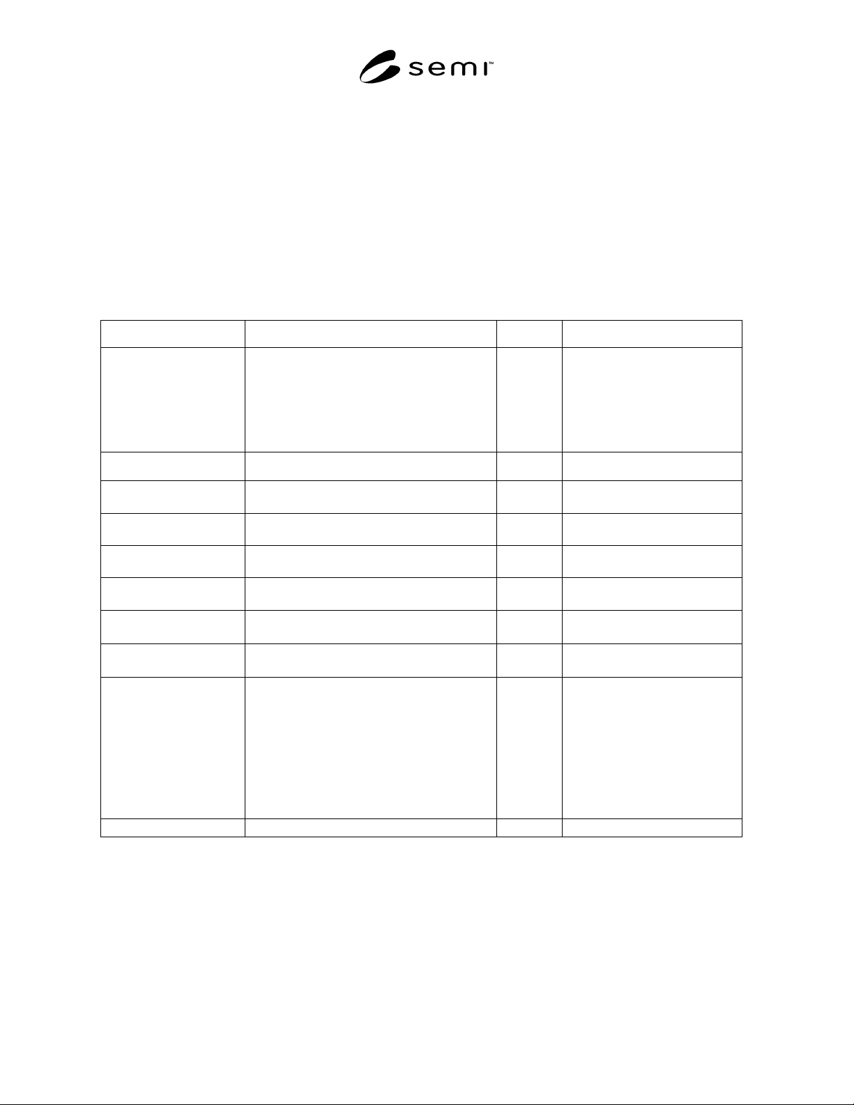
11.2.6 Component Descriptions and Allowed Formats
Table 6 Process Program Component Description and Format Table
Component Name Description Format Comments
ALIGN-ATTRIBUTE
(n)
Tool specific information associated with
alignment site for which no specific MSEM
data item has been defined.
Examples include information
such as magnification, voltage,
current, wavelength, number of
scans, integration time, or film
stack. The equipment supplier
shall document all attributes
that are supported.
ALIGN-NAME The identifier given to a alignment site. A[1..16]
COORDSYS The identification for applicable coordinate
system.
A[1..16] Options for silicon wafers are:
SEMI M20, M20P, SEMI M21
COORDX The x coordinate for a site or the lower left
hand corner of an element.
F4 Units are in microns.
COORDY The y coordinate for a site or the lower left
hand corner of an element.
F4 Units are in microns.
ELEMENTID The element identifier in the SEMI M21
coordinate system
U4[2]
M21XSIZE The SEMI M21 element size in the x direction
in µm.
F4
M21YSIZE The SEMI M21 element size in the y direction
in µm.
F4
SITE-ATTRIBUTE
(n)
Tool specific information associated with a
measurement site for which no specific
MSEM data item has been defined.
Examples
include information such as
magnification, voltage, current,
wavelength,
number of scans, integration
time, or film stack. The
equipment supplier
shall document all attributes
that are supported.
SITENAME A unique identifier for a site. A[1..16]
11.2.7 DEF-LIST-TABLE Description
DEF-LIST types of tables are used by the equipment in conjunction with
the Process Programs. The DEF-LIST table structures provide a means to transfer to equipment a list of a particular
type of information. The DEF-LIST table structures are used by the host to send information to equipment for later
use in association with a Process Program. Each DEF-LIST that is sent has a unique Table name and each list
element in the DEF-LIST has several components including a name (Site-Name, or Align-Name) as well as other
components. A specific list row can be accessed for use with a specific Process Program by giving the DEF-LIST
table name and the specific row name.