semi合集-English.pdf - 第6876页
SEMI S3-91 © SEMI 199 1, 1996 3 6.3 Joseph Lotti, “ E lectric Im mers i o n Heater Redundan t Control Syst e m”, presen ted to Semiconductor Safe ty Ass ociation Annual C onference, May 1986. 6.4 Factory Mutual Insurance…

SEMI S3-91 © SEMI 1991 2
accordance with the manufacturer’s recommendations
should be performed.
4.5 Liquid Level Sensor — This sensor will act to shut
down the heating element if the liquid level falls below
a safe operating level. When employing either an
immersion or externally mounted type heater, it is
recommended that this level be no less than five
centimeters (two inches) above the heating element’s
“hot zone” as established by the manufacturer. This
should prevent the element from losing the heat sink
created by the liquid.
4.5.1 The selection of a suitable sensor should take
into account:
4.5.1.1 The physical properties of the liquids being
heated and the environmental conditions to which the
sensor(s) will be subjected.
4.5.1.2 The mode of failure, if the sensor fails.
4.5.2 To preserve the integrity of these components,
they should be tested on a quarterly basis and serviced
following the manufacturer’s recommendations.
4.6 Overtemperature Protection
4.6.1 Liquid Overtemperature — A dedicated liquid
overtemperature sensor should typically be set to trip at
a temperature below the autoignition temperature of the
chemical being used in the bath, and in no case higher
than 10°C (18°F) above the normal operating
temperature.
4.6.1.1 This temperature setting should compensate
for the initial over-shoot often encountered when
bringing the liquid from ambient to operating
temperature.
4.6.1.2 The sensor should be located in the liquid at an
elevation approximating the top of the heating elements
“hot zone” and no more than seven centimeters (three
inches) away from the heater.
4.6.2 Heating Element Overtemperature — When
using an electrical immersion type heater, a sensor
should be used to shut down the heating element if the
surface temperature of the element exceeds a preset
value. The sensor is typically placed between the
resistance coil and the protective sheath covering.
4.7 Proper Grounding & Ground Fault Protection —
The amount of insulation surrounding a heater element
depends upon the type of heater. This insulation not
only provides protection from the corrosive properties
of the solution, but also acts as an electrical barrier. If
the barrier breaks down, it is possible for the solution to
become energized.
4.7.1 The electric heater elements should be equipped
with a ground, the construction of which should be
approved by a nationally recognized testing laboratory
(NRTL).
4.7.2 A ground fault circuit interrupter (GFCI) should
be used to preclude worker exposures to potential
electrical shock.
4.7.3 The station or equipment in which the heated
bath will be used needs to be reviewed to ensure that all
National Electrical Code requirements have been
addressed.
4.8 Compatible Construction Materials — All
portions of the station that could come in contact with
process chemicals should be constructed from materials
compatible with these chemicals. It is recommended
that metal materials be used in the station’s construction
when using combustible or flammable solutions.
5 Operation and Maintenanc e
5.1 Before heated baths are put into service, a detailed
review of the wet station operation and maintenance
should be conducted for all employees operating or
servicing the station. New employees should receive the
same information prior to work assignment.
5.1.1 All safety features included with the station’s
heating system should be user tested, and the frequency
of testing should be noted in the user’s periodic
maintenance procedures.
NOTE: Recommended minimum frequency of testing is
quarterly and after any station maintenance.
5.1.2 Vendor-supplied information on the bath
operation and limitations that may apply should be
reviewed and appropriate employee training conducted.
5.1.3 When the user plans to install the baths and to
perform maintenance, the suppliers should provide
guidance to ensure that all aspects of the system, such
as the controller and the heated bath safety systems, are
integrated properly.
5.1.4 Review the process requirements to ensure that
operating temperatures are within the range and
capability of the safety controls. For flammable and
combustible liquids, operating temperatures should be
below the ignition temperature.
5.1.5 Limit the interchanging of parts that were not
included in the original design unless so advised by the
supplier. Alternate parts can lead to failures resulting in
a fire or physical injury.
6 Related Documents
6.1 UFC 1988 edition.
6.2 OSHA Safety & Health Standards (29 CFR 1910).

SEMI S3-91 © SEMI 1991, 19963
6.3 Joseph Lotti, “Electric Immersion Heater
Redundant Control System”, presented to
Semiconductor Safety Association Annual Conference,
May 1986.
6.4 Factory Mutual Insurance Corporation, “Plastics
and Plastic-Lined Tanks with Electric Immersion
Heaters,” 7-6.
6.5 National Electrical Code, “Articles 500, 501,
Hazardous Locations,” latest edition.
6.6 National Electrical Code, “Art icles 250, 422, 427,
and 516, Grounding, Appliances, Fixed Electrical
Heating for Pipe Lines and Vessels and Spray
Application, Dipping and Coating Processes.”
6.7 SEMI S2, Safety Guidelines for Semiconductor
Manufacturing Equipment.
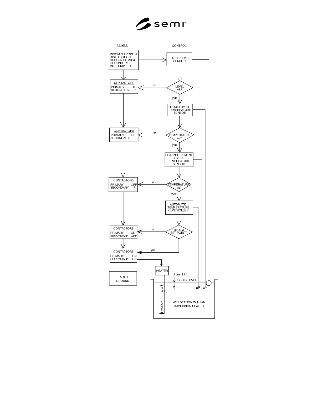
SEMI S3-91 © SEMI 1991 4
Figure 1