semi合集-English.pdf - 第7098页
SEMI S20-0303 © SEMI 2003 7 RELATED INFORMATION 1 EXAMPLES OF GRAPHICAL REPRESENTATIONS NOTICE: This Related Inform ation is not an official part o f SEMI S20. It was de rived from AMD activi ty, but is generic and no t …

SEMI S20-0303 © SEMI 2003 6
NOTICE: SEMI makes no warranties or representations as to the suitability of the standard set forth herein for any
particular application. The determination of the suitability of the standard is solely the responsibility of the user.
Users are cautioned to refer to manufacturer’s instructions, product labels, product data sheets, and other relevant
literature respecting any materials or equipment mentioned herein. These standards are subject to change without
notice.
By publication of this standard, SEMI takes no position respecting the validity of any patent rights or copyrights
asserted in connection with any item mentioned in this standard. Users of this standard are expressly advised that
determination of any such patent rights or copyrights, and the risk of infringement of such rights, are entirely their
own responsibility.
SEMI S20-0303 © SEMI 2003 7
RELATED INFORMATION 1
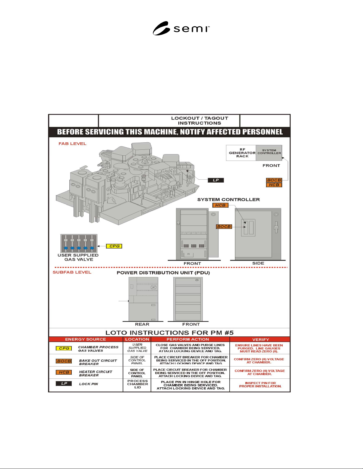
EXAMPLES OF GRAPHICAL REPRESENTATIONS
NOTICE: This Related Information is not an official part of SEMI S20. It was derived from AMD activity, but is
generic and not copyrighted. This related information was approved for publication by inclusion in the ballot and by
vote of the SEMI Standards EHS Committee. It is included to assist the user of the document in understanding what
the graphical representations should provide in the way of information and location identification.
R1-1 Drawings
SEMI S20-0303 © SEMI 2003 8
RELATED INFORMATION 2
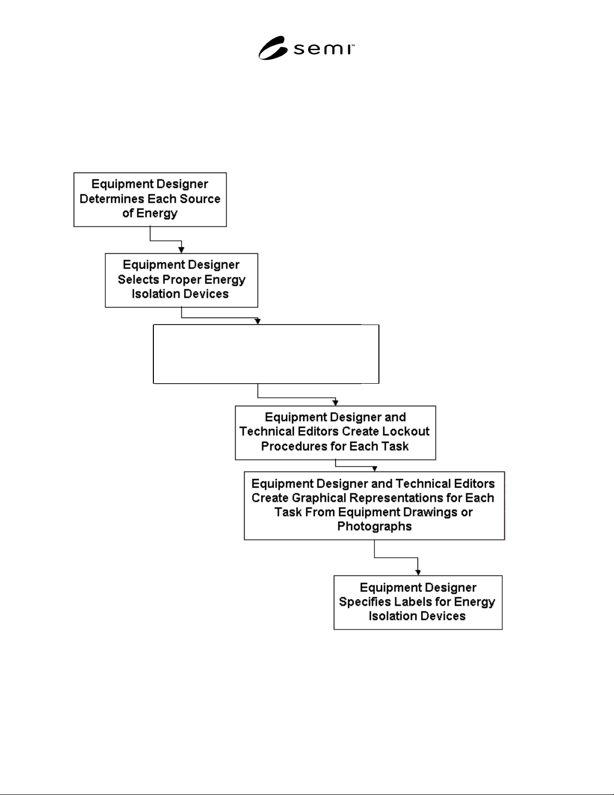
EXAMPLE FLOW FOR HAZARDOUS ENERGY CONTROL DESIGN
NOTICE: This Related Information is not an official part of SEMI S20 but was derived from task force activity.
This related information was approved for publication by inclusion in the ballot and by vote of the SEMI Standards
EHS Committee. It is included to assist the user of the document in understanding what the graphical
representations should provide in the way of information and location identification.
Equipment Designer Specifies Which
Lockout Devices are Necessary for
Energy Control for Each Task
Figure R2-1
Flow Chart for HEC Design and Graphical Representation Generation