semi合集-English.pdf - 第2309页
SEMI E82-0705 © SEMI 1999, 2005 5 7.2 TSC St ate Model 7.2.1 TSC State Model Requirements 7.2.1.1 Th e purpose of the Transport System state model is to provid e information to the host regarding the overall status of th…
SEMI E82-0705 © SEMI 1999, 2005 4
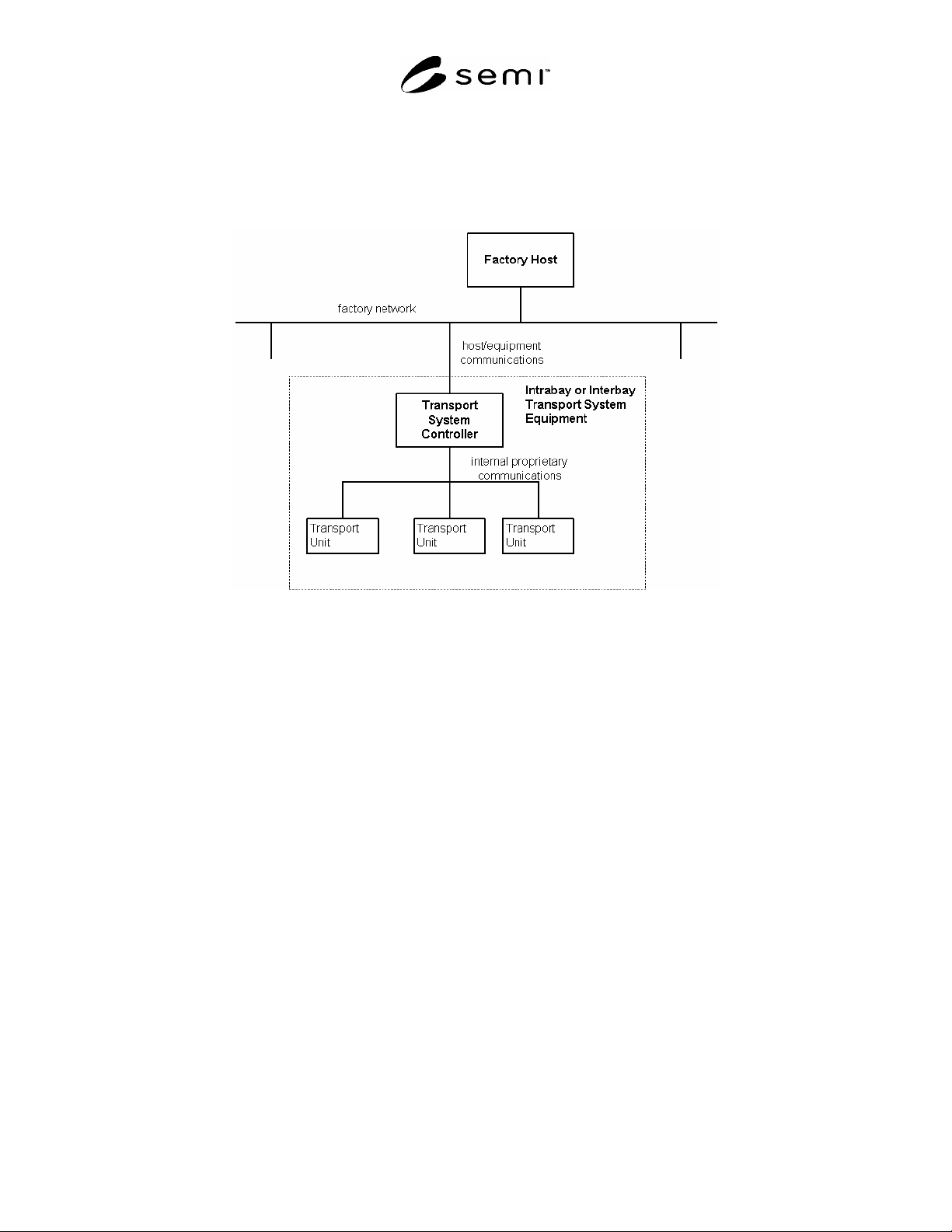
5.2.17 Transport System Equipment — an individual transport system viewed as a single piece of equipment, with
distributed components and distributed control. The TS controller communicates with the host using HSMS and
GEM and represents the system as an equipment. The factory may require more than one type of transport system.
5.2.18 transport unit — a physical component of a transport system, such as a vehicle, node, or docking unit.
Figure 1
Example of Transport System Equipment
6 Communication Requirements
6.1 It is required that any IBSEM compliant equipment follow the Communications State Model in SEMI E30. In
addition, IBSEM compliant equipment shall support either the High-speed SECS Message Services Single-Session
Mode (SEMI E37 and SEMI E37.1, HSMS and HSMS-SS) communication standard or SEMI Equipment
Communications Standard 1 Message Transfer (SEMI E4, SECS-I) communication standard.
7 State Models
7.1 State Model Requirements
7.1.1 The state models included in this standard are a requirement for IBSEM equipment. This standard requires
implementation of all SEMI E30 state models (such as control, communication, on-line/off-line, etc. according to
the GEM capabilities required per §13). A state model consists of a state model diagram, state definitions, and a
state transition table. All state transitions in this standard, unless otherwise specified, shall correspond to collection
events.
7.1.2 A state model is the host’s view of the equipment, and does not necessarily describe the internal equipment
operation. All IBSEM state model transitions shall be mapped into the appropriate internal equipment events that
satisfy the requirements of those transitions. In certain implementations, the equipment may enter a state and have
already satisfied all of the conditions required by the IBSEM state model for transition to another state. The
equipment makes the required transition without any additional actions in this situation.
7.1.3 Some equipment may need to include additional substates other than those in this standard. Additional
substates may be added, but shall not change the IBSEM defined state transitions. All expected transitions between
IBSEM states shall occur.
SEMI E82-0705 © SEMI 1999, 2005 5
7.2 TSC State Model
7.2.1 TSC State Model Requirements
7.2.1.1 The purpose of the Transport System state model is to provide information to the host regarding the overall
status of the Transport System. The TSC state model is valid when the SEMI E30 (GEM) state is ON-LINE. The
TSC state model is not valid when the SEMI E30 (GEM) state is OFF-LINE. Since a transport system may consist
of many components (e.g., vehicle, robot arm, ID reader, etc.), it may be possible to continue ON-LINE operation
when the operation mode of some transport components (as viewed by the TSC) is a manual state. The details of
what happens when individual components of the transport system enter a manual state are specific to the IBSEM
equipment supplier. When the SEMI E30 Control state changes from OFF-LINE to ON-LINE, the TSC State Model
is started from the TSC INIT state.
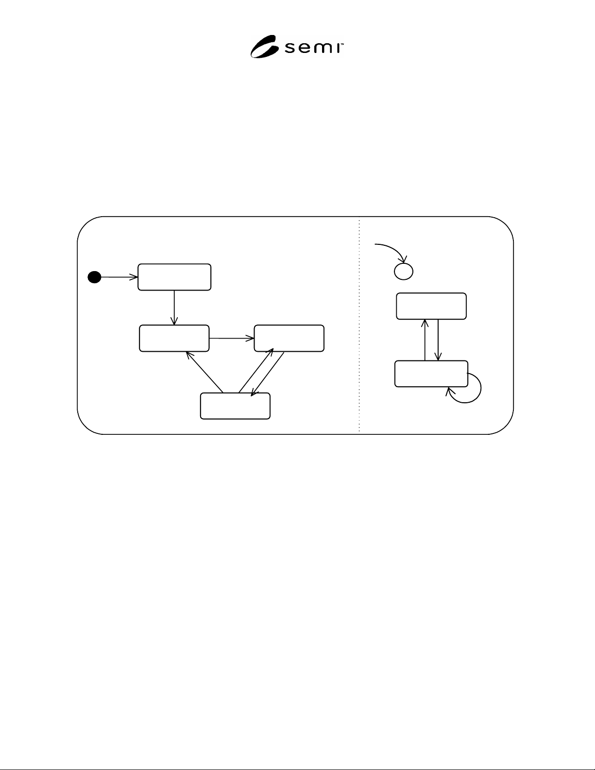
7.2.2 TSC State Model
PAUSED
PAUSING
AUTO
ALARMS
NO ALARMS
TSC INIT
6
3
4
8 7
AVAILABILITY
SYSTEM
5
2
1
9
C
Figure 2
Generic IBSEM TSC State Model Diagram
7.2.3 TSC State Definitions
7.2.3.1 TSC INIT — TSC initialization of TS components is occurring. This is a non-operational state. No
commands from the host will be processed or queued. The system will not move out of this state if there are
vehicles actively loading or unloading carriers at ports. These vehicles must be manually or automatically recovered
before moving on to the next state.
7.2.3.2 PAUSING — A system PAUSE command has been received and is being processed. All vehicles that are
currently loading or unloading will continue until the load/unload is complete. Vehicles that are currently moving
may continue to move but they must not begin a load or unload. TRANSFER commands are accepted and queued.
All status requests will be processed. The RESUME command will also be processed.
7.2.3.3 PAUSED — No vehicles are in the process of loading or unloading a carrier at a port, but vehicles may still
be moving. TRANSFER commands are accepted and queued. All status requests will be processed. The RESUME
command will also be processed.
7.2.3.4 AUTO — System is in the normal operational state. Commands are actively processed.
7.2.3.5 NO ALARMS — There are no alarms present in the system.
7.2.3.6 ALARMS — There are one or more alarms present in the system, but the TSC is still capable of normal
processing since several components may remain unaffected by the alarm situation.

SEMI E82-0705 © SEMI 1999, 2005 6
7.2.4 TSC State Transition Table
Table 1 TSC State Transition Table
Transition # Previous State Trigger New State Actions Comments
1 None TSC Initiation. TSC INIT S6F11
TSCAutoInitiated
System runs through its
startup sequence.
2 TSC INIT System started up
successfully. All loads
and unloads are complete.
PAUSED S6F11
TSCPaused
System ready.
3 PAUSED TSC is resumed. AUTO S6F11
TSCAutoCompleted
System will now perform
all commands. Stopped
Vehicles will resume
normal motion.
4 AUTO TSC is requested to
pause.
PAUSING S6F11
TSCPauseInitiated
Vehicles that are stopped
stay stopped. Vehicles that
are moving stop at the next
logical point without
proceeding.
5 PAUSING TSC is resumed. AUTO S6F11
TSCAutoCompleted
System will now perform
all commands. Stopped
Vehicles will resume
normal motion.
6 PAUSING All carrier loads and
unloads are completed.
No new acquires or
deposits will occur.
Outstanding acquires and
deposits will complete.
PAUSED S6F11
TSCPauseCompleted
System will accept and
queue new commands but
will not execute them.
7 NO ALARMS Alarm Set. ALARMS S6F11
AlarmSet
System can process
normally for transport
components that are
unaffected by the alarm.
8 ALARMS Last remaining alarm
cleared.
NO ALARMS S6F11
AlarmCleared
9 ALARMS Alarm Set. ALARMS S6F11
AlarmSet
Alarm occurs when there is
already an outstanding
alarm.
7.3 TRANSFER Command State Model
7.3.1 TRANSFER Command State Model Requirements
7.3.1.1 The TRANSFER command state model serves as the SEMI E30 Processing State Model. The purpose of
the TRANSFER command state model is to provide information to the host regarding the control of the TRANSFER
command. The TRANSFER command allows the host to manage interbay or intrabay delivery and scheduling. The
control of each TRANSFER command must independently support the TRANSFER command state model.
7.3.2 TRANSFER Command State Model Diagram
7.3.2.1 The TRANSFER command state model is detailed for IBSEM equipment in Figure 3.