semi合集-English.pdf - 第3522页
SEMI E134.1-0305 © SEMI 2005 9 Figure 1 XML Schema Example Diagram 6.4 XML Schema Sam ple 6.4.1 The sam ple XML Schema for the exampl e shown in Figu re 1, is presented below. Refer to the XML documenta tion refere nced …
SEMI E134.1-0305 © SEMI 2005 8
6.3 Documenting XML Schema With Diagrams
6.3.1 This document provides graphical representations of the included XML Schema data type and element
definitions. Although no standard graphical notation for XML Schema could be found, various XML tools have
their own notation. This document will use the notation provided by XMLSpy from Altova Corporation Table 1
shows a sample XML Schema diagram that will be used to provide a basis for explanation of the schema graphical
notation used in the rest of the document.
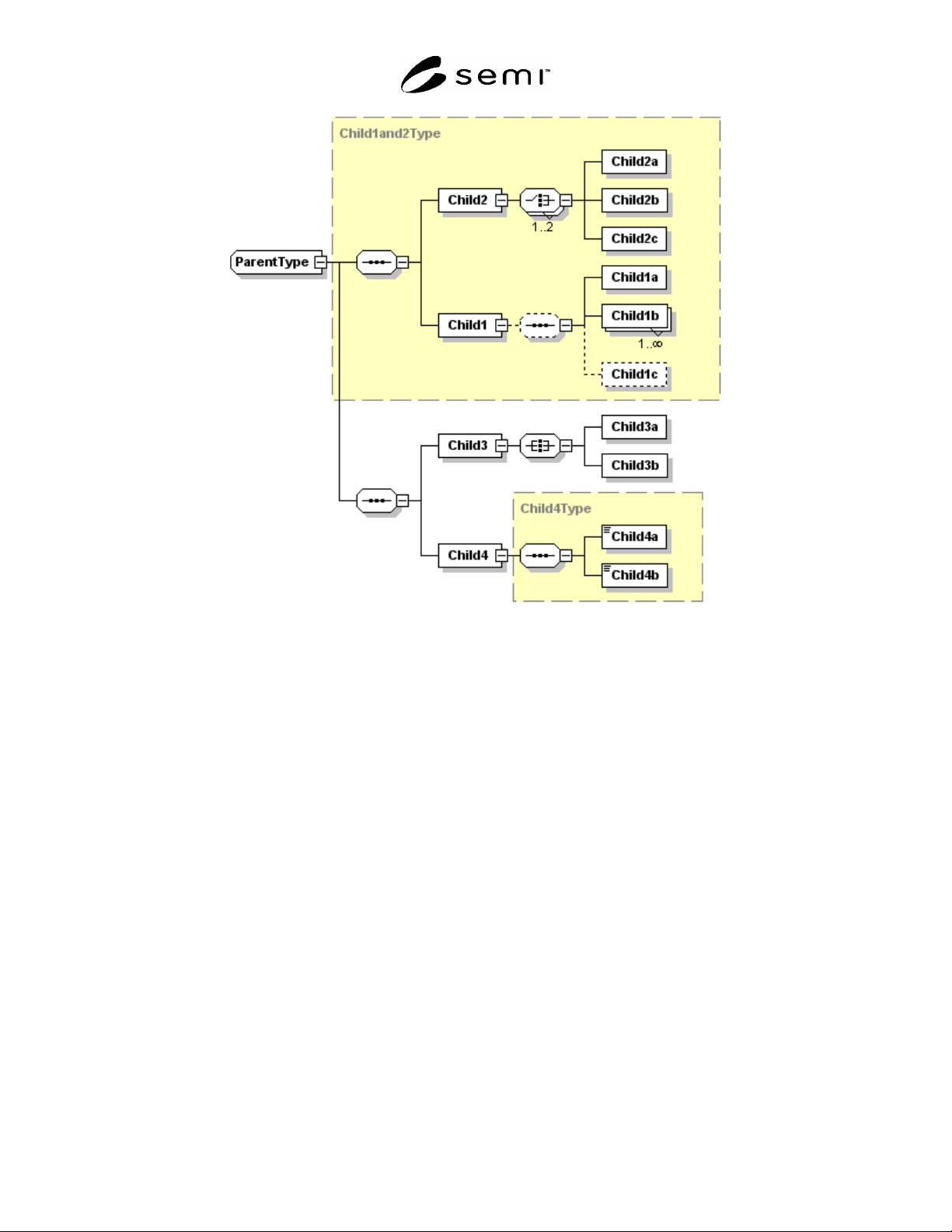
6.3.2 In the diagram, rectangular boxes represent XML element definitions. Ownership or containment is read from
left to right in the diagrams. In the sample diagram, ParentType contains Child1, Child2, Child 3, and Child 4. In
turn, Child2 contains Child2a, Child2b, and Child2c. The additional symbols (8-sided boxes) represent sequences or
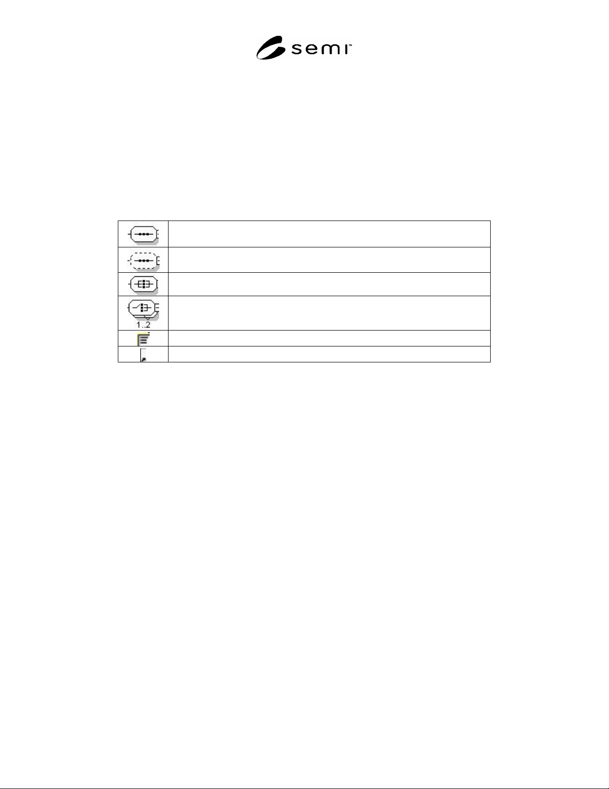
choices. See Table 4 for an explanation of these symbols.
Table 4 Altova XMLSPY Schema Diagram Symbols
Denotes a required ordered sequence of the right hand elements with a cardinality of one
for each element. (sequence)
Denotes an optional ordered sequence of the right hand elements with a cardinality of
one for each element. (sequence)
Denotes a required, but unordered, sequence of the right hand elements with a
cardinality of one for each element. (all)
Denotes a required choice of the right hand elements. Exactly one or two of the right
hand elements must be present. (choice)
Denotes an element that contains parsed character data
Denotes a reference to a group or element defined elsewhere
6.3.3 A graphic using a solid line is a required element; using a dashed line represents an optional element. Numbers
or ranges in the lower right hand corner represent cardinality. The default cardinality is one.
6.3.4 To simplify a diagram or help focus on a particular aspect, detail may be hidden. The 8-sided symbols have a
small square on the right end. If a minus sign “-” is in the box, then all detail is shown. If the box contains a plus
sign “+”, then all detail to the right of that symbol is hidden. The example has no hidden detail.
6.3.5 The yellow (or grey if printed in monochrome) boxes indicate the use of other defined types. So, Child4 is of
type “Child4Type”. Child4Type defines Child4a and Child4b. This detail may be hidden in the diagram. Object
oriented inheritance is typically represented in XML as type extension. In Figure 1, ParentType extends
Child1and2Type by adding a sequence that includes Child3 and Child4.
6.3.6 Reading Figure 1 would yield the following additional information:
1. Child1and2Type is an ordered sequence of two items: Child2 and Child1.
2. Child1 contains an optional ordered sequence of Child1a, one or more Child1b, and (optionally) Child1c.
3. Child2 contains a choice of one or two of the following: Child2a, Child2b, and Child2c.
4. Child3 contains an unordered sequence of Child3a and Child3b.
SEMI E134.1-0305 © SEMI 2005 9
Figure 1
XML Schema Example Diagram
6.4 XML Schema Sample
6.4.1 The sample XML Schema for the example shown in Figure 1, is presented below. Refer to the XML
documentation referenced in ¶4.3 for a complete description of the syntax and semantics of XML Schema.
SEMI E134.1-0305 © SEMI 2005 10
<xs:element name="Parent">
<xs:complexType>
<xs:sequence>
<xs:element name="Child1"/>
<xs:complexType>
<xs:sequence minOccurs="0">
<xs:element name="Child1a"/>
<xs:element name="Child1b" maxOccurs="unbounded"/>
<xs:element name="Child1c" minOccurs="0"/>
</xs:sequence>
</xs:complexType>
</xs:element>
<xs:element name="Child2">
<xs:complexType>
<xs:choice maxOccurs="2">
<xs:element name="Child2a"/>
<xs:element name="Child2b"/>
<xs:element name="Child2c"/>
</xs:choice>
</xs:complexType>
</xs:element>
<xs:element name="Child3">
<xs:complexType>
<xs:all>
<xs:element name="Child3a"/>
<xs:element name="Child3b"/>
</xs:all>
</xs:complexType>
</xs:element>
</xs:sequence>
</xs:complexType>
</xs:element>
Figure 2
XML for Sample
6.5 Translating UML to WSDL
6.5.1 In general, UML interface classes defined in the abstract specification are translated into WSDL as portType
definitions, and each portType definition has a corresponding WSDL binding definition. The following tables show
the convention used for documenting the WSDL port type and binding definitions for a given UML interface class.
Table 5 Example Interface WSDL Port Type Table
Class Name <UML interface name from abstract specification>
WSDL Port Type Name <port type name used in WSDL>
SEMI E125 Operation
WSDL Operation
<operation name from UML interface> <WSDL port type operation name>
Table 6 Example Interface WSDL Binding Table
SEMI E125 Class Name <UML interface name from abstract specification>
WSDL Binding Name <binding name used in WSDL>
SOAP Binding Style <RPC or document>
SOAP Transport <transport identifying URI>