semi合集-English.pdf - 第6335页
1 SEMI G66-96 © SEMI 1996, 2004 SEMI G66-96 (Reapproved 1104) TEST METHOD FOR THE MEASUR EMENT OF WATER ABSORPTI ON CHARACTERISTICS FOR SEMICO NDUCTOR PLASTIC MOLDING COMPOUNDS This test method was technicall y approved …

7 SEMI G65-96 © SEMI 1996, 2004
NOTE 4: Perform this operation carefully to avoid reforming
the leads.
11.3.2 Select two (2) leads from one sample.
11.3.3 Observe the outside surface of the lead and take
a photograph with a microscope set at 75×
magnification.
11.3.4 Set the lead sample in a projector.
11.3.5 Project the picture of the sample on the screen.
11.3.6 Adjust the protractor to the picture and read the
form angle.
12 Calculation
12.1 Calculate the spring back value as follows:
12.1.1 Spring back = actual angle of sample - designed
form angle
12.2 Calculate the average spring back value.
12.3 Round the result to one significant figure.
13 Report
13.1 The report shall contain the following
information:
13.1.1 Leadframe material name, lot number, and
vendor
13.1.2 Average thickness (per Section 10.2)
13.1.3 Photograph taken using 75× magnification (per
11.3.3)
13.1.4 List of observations (per Section 11.3.3)
NOTE 5: Classify observation results as crack, orange peel,
and good according to their definition in Section 4. If
required, further classification should be agreed between
customer and vendor.
13.1.5 Spring Back Value (per Sections 11.3.4 to
11.3.6) — Average, minimum, maximum
13.1.6 Rejection — The limit shall be agreed between
user and supplier.
14 Related Documents
14.1 SEMI Specification
SEMI G4 — Specification for Integrated Circuit
Leadframe Materials Used in the Production of
Stamped Leadframes
14.2 JIS Specifications
JIS-Z-2248 — Method of Bend Test for Metallic
Materials
JIS-H-3130 — Copper Beryllium Alloy, Phosphor
Bronze and Nickel Silver Sheets, Plates, and Strips for
Springs
14.3 CES Specification
M0002-6 — Test Method of W Bend for Metallic
Materials
NOTICE: SEMI makes no warranties or
representations as to the suitability of the standard set
forth herein for any particular application. The
determination of the suitability of the standard is solely
the responsibility of the user. Users are cautioned to
refer to manufacturer’s instructions, product labels,
product data sheets, and other relevant literature
respecting any materials or equipment mentioned
herein. These standards are subject to change without
notice.
By publication of this standard, SEMI takes no position
respecting the validity of any patent rights or copyrights
asserted in connection with any item mentioned in this
standard. Users of this standard are expressly advised
that determination of any such patent rights or
copyrights, and the risk of infringement of such rights,
are entirely their own responsibility.
Copyright by SEMI® (Semiconductor Equipment and Materials
International), 3081 Zanker Road, San Jose, CA 95134. Reproduction of
the contents in whole or in part is forbidden without express written
consent of SEMI.
1 SEMI G66-96 © SEMI 1996, 2004
SEMI G66-96 (Reapproved 1104)
TEST METHOD FOR THE MEASUREMENT OF WATER ABSORPTION
CHARACTERISTICS FOR SEMICONDUCTOR PLASTIC MOLDING
COMPOUNDS
This test method was technically approved by the Global Assembly & Packaging Committee and is the direct
responsibility of the Japanese Packaging Committee. Current edition approved by the Japanese Regional
Standards Committee on July 23, 2004. Initially available at www.semi.org September 2004; to be published
November 2004. Originally published in 1996.
1 Purpose
1.1 This method describes a procedure for measuring
the water absorption rate for plastic molding
compounds and provides a method to calculate the
diffusion and solubility coefficients, which are required
to simulate the water absorption characteristics.
2 Scope
2.1 This method may be applied to all semiconductor
plastic molding compounds.
2.2 This method may be used to characterize molding
compounds in development.
2.3 Packaging engineers may simulate the water
absorption characteristics and their significance in
relation to package cracks at soldering by using
calculated diffusion and solubility coefficients.
NOTICE: This standard does not purport to address
safety issues, if any, associated with its use. It is the
responsibility of the users of this standard to establish
appropriate safety and health practices and determine
the applicability of regulatory or other limitations prior
to use.
3 Referenced Standards
3.1 None.
4 Terminology
4.1 Definitions
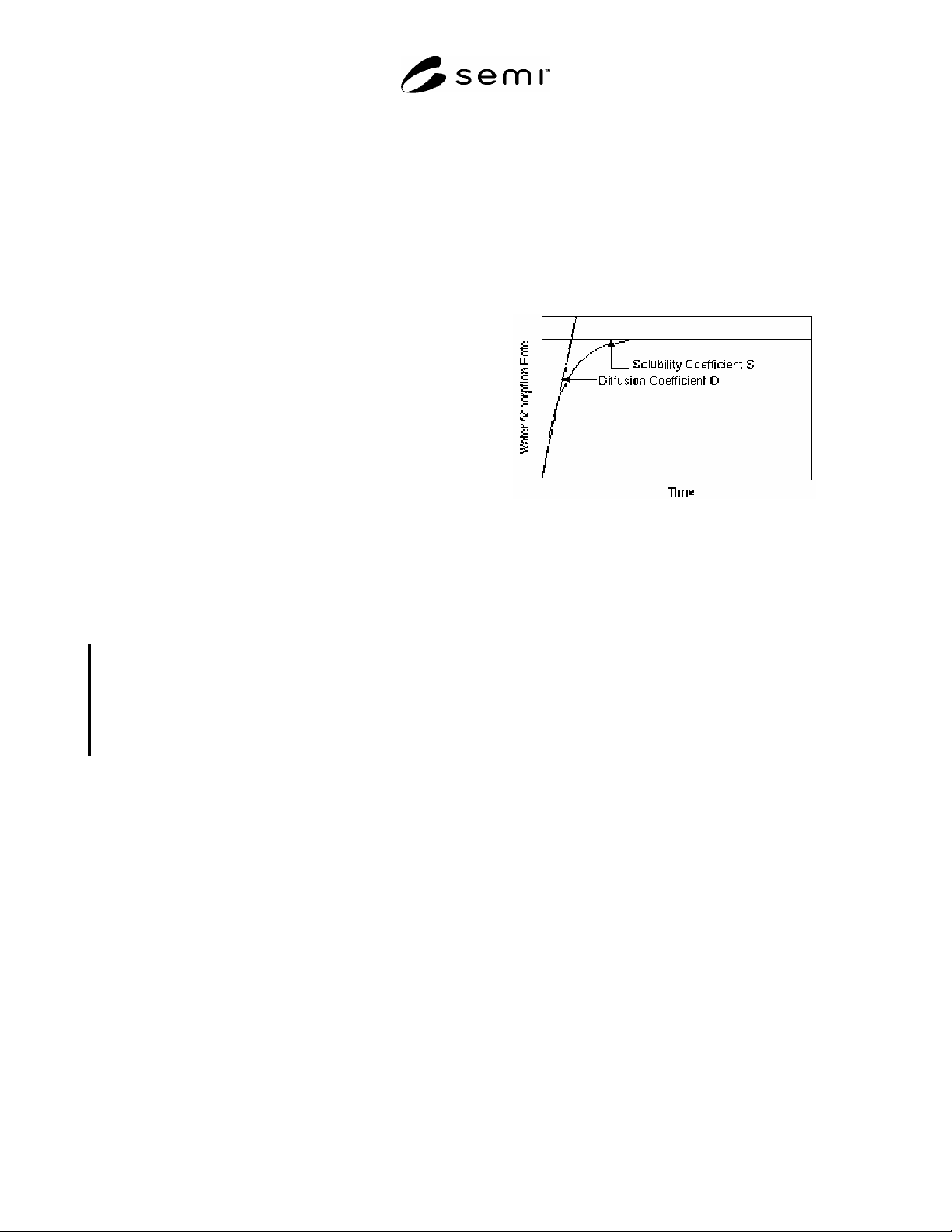
4.1.1 diffusion coefficient, D — the diffusion rate of
water into a molding compound (see Appendix 1 and
Figure 1).
4.1.2 solubility coefficients, S — ratio of saturated
moisture concentration in molding compounds to partial
pressure of moisture in environment (see Appendix 1
and Figure 1).
Figure 1
Concept of Diffusion and Solubility Coefficients
5 Summary of Method
5.1 This method is based on the measurement of the
increase in weight, due to water absorption, after
exposing the molding compound to a high-temperature,
high-humidity environment.
6 Equipment
6.1 Balance — An analytical balance capable of
reading 0.0001g.
6.2 High-Temperature Chamber — Capable of
maintaining a uniform temperature of 125 ± 3°C.
6.3 Temperature/Humidity Chamber — Capable of
maintaining a uniform temperature of 85 ± 2°C and 85
± 5% relative humidity.
6.4 Desiccator (1) — To hold specimens during cool-
down from high-temperature conditioning.
6.5 Desiccator (2) — This desiccator, with water in the
bottom rather than drying compound, is to hold the
specimens after exposure to heat and humidity.
6.6 Mold for specimen preparation.
7 Reagents and Materials
7.1 Deionized Water — Resistivity 15M ohm-cm at
25°C

SEMI G66-96 © SEMI 1996, 2004 2
8 Sampling Plan
8.1 At least three samples shall be chosen for each
molding type for each test.
9 Test Specimens
9.1 Test specimens are required as follows:
9.1.1 Specimens for diffusion area.
9.1.1.1 Diameter — 50 ± 1 mm
9.1.1.2 Thickness — 3 ± 0.2 mm
9.1.2 Specimens for saturated area.
9.1.2.1 Diameter — 50 ± 1 mm
9.1.2.2 Thickness — 1 ± 0.2 mm
10 Equipment Set-Up
10.1 Refer to manufacturer’s operation manuals.
11 Procedure
11.1 Specimen Preparation
11.1.1 Prepare the specimens by molding samples
using the specimen mold and conditions recommended
by the molding compound manufacturer.
11.1.2 Post-mold cure the specimens to recommended
conditions using the high-temperature chamber.
11.2 Specimen Conditioning
11.2.1 Dry the specimens at 125°C in the high-
temperature chamber for 24 hours minimum.
NOTE 1: If the samples are already dry (e.g., samples
directly from post-mold cure), additional conditioning is not
required.
11.2.2 Place the specimens in the desiccator (1) and
allow to cool to room temperature.
11.2.3 Weigh the specimens to the nearest 0.0001g.
11.3 Water Absorption Exposure and Reconditioning
11.3.1 Diffusion Area
11.3.1.1 Place the conditioned specimens (3 mm
thickness) in the high-temperature/humidity chamber
set at 85°C and 85% relative humidity for 24 ± 1 hours.
NOTE 2: The specimens should be placed to avoid any
contact with each other and with the walls of the chamber,
e.g. to use a holder or to place on a wire net.
11.3.1.2 Remove the specimens from the chamber and
wipe off any excess water from the surfaces with a
clean cloth or absorbant paper.
11.3.1.3 Place the specimens in desiccator (2) and
allow to cool to room temperature.
NOTE 3: The specimens should be placed to avoid any
contact with each other and with the walls of the chamber
(e.g., to use a holder or to place on a wire net).
11.3.1.4 Re-weigh the specimens to the nearest 0.0001
g.
11.3.2 Saturated Area
11.3.2.1 Place the conditioned specimens (1 mm
thickness) in the high-temperature/humidity chamber
set at 85°C and 85% relative humidity for 168 ± 4
hours.
NOTE 4: The specimens should be placed to avoid any
contact with each other and with the walls of the chamber
(e.g., to use a holder or to place on a wire net).
11.3.2.2 Remove the specimens from the chamber and
wipe off any excess water from the surfaces with a
clean cloth or absorbant paper.
11.3.2.3 Place the specimens in desiccator (2) and
allow to cool to room temperature.
NOTE 5: The specimens should be placed to avoid any
contact with each other and with the walls of the chamber,
e.g. to use a holder or to place on a wire net.
11.3.2.4 Re-weigh the specimens to the nearest
0.0001g.
12 Calculations
12.1 Water Absorption Rate — The rate is calculated as
follows:
12.1.1 Water absorption rate (wt%) = ( (M2 M1) /M1)
× 100 (1)
Where:
M1 is the initial conditioned weight, and
M2 is the reconditioned weight after exposure to
temperature/humidity
12.2 Diffusion and Solubility Coefficients
12.2.1 There are various methods to calculate diffusion
and solubility coefficients. See Appendix 1 for one of
these methods.
13 Report
13.1 The following information shall be reported:
13.1.1 Manufacturer and identification of molding
compound
13.1.2 Specimen sizes
13.1.3 Test conditions
13.1.4 Water absorption rate