semi合集-English.pdf - 第5365页
SEMI M54-0304 © SEMI 2003, 2004 6 SEMI MF523 — Standard Practice for Unaided Visual Inspection of Polished Silicon Wafer Surfaces SEMI MF1241 — Standard Terminology of Silicon Technology 7.2 Other Docs 5 DIN 50443-2 — Te…

SEMI M54-0304 © SEMI 2003, 2004 5
methods include GDMS, SSMS, Secondary Ion Mass
Spectroscopy (SIMS) and atomic absorption
spectroscopy (AAS).
5.14 Surface contaminants are identified and quantified
with Time-of-Flight-SIMS (TOF-SIMS) and Total
Reflection X-Ray Fluorescence (TXRF). The latter
technique is difficult to apply for impurities with atomic
weight below those of the matrix elements Ga and As.
5.15 Deposition of high quality epitaxial layers without
chemical pre-cleaning depends on the surface oxide
structure of the substrate, as prepared by the supplier, as
well as the thermal oxide desorption and the epitaxial
deposition procedures of the purchaser. Hence an
individual supplier-purchaser specific evaluation is
necessary. Test epitaxy followed by layer quality
assessment is recommended.
5.16 The lateral substrate homogeneity is assessed by
automated analytic instrumentation elaborated to
generate topographic images of important material
parameters, including electrical resistivity, EL2
concentration, EPD and minority carrier lifetime.
Macroscopic (e.g. radial) variations as well as
mesoscopic fluctuations (generally correlated to the
cellular dislocation structure) may be assessed. Such
topographic analysis is provided, respectively, by
contactless capacitive resistivity mapping (see DIN
50448), EL2 absorption topography (see footnote 3),
specular light reflection topography and
photoluminescence topography. The first three
topography techniques provide quantitative data.
Photoluminescence topography gives qualitative
homogeneity information only, because the
interrelations between the luminescence intensity and
the various radiative and nonradiative recombination
processes are only partially understood. The details of
the topographic measurements, i.e. lateral resolution
and edge exclusion, must be defined by individual
supplier-purchaser agreement.
5.17 As precipitates, other inclusions and voids are
visualized with light scattering tomography (LST). At
present it is not possible to differentiate between these
scattering centers and to obtain quantitative information
concerning their concentration and size. Hence LST
images provide a qualitative information only.
5.18 Micro-roughness, also referred to as haze, is
indicated by a diffuse reflection of collimated, laterally
extended high intensity illumination from the wafer
surface. Localized haze and haze observed on
particular wafers of a batch indicate potentially
disadvantageous variations of surface quality. The
agreement should specify the conditions of observation
(e.g. illumination intensity).
5.19 Surface irregularities (stain, scratches, pits, orange
peel, dimples) are identified by high intensity
illumination or by standard and phase sensitive
(Nomarski) microscopy. Individual agreement is
recommended concerning the permitted surface density
of these defects.
6 Ordering Information
6.1 The material properties of SI GaAs substrates, as
described in Section 4, are addressed in the ordering
agreement using the tables given below. The
subdivisions into “important”, “optional” and “other”
specifications are suggested only, i.e. supplier and
purchaser may agree on an individual choice, taking
into account the respective application as well as cost
considerations.
6.2 In addition to specifying individual material
properties as listed below, the purchase order may
specify the fabrication procedures according to Sections
4.2 and 4.3.
6.3 Substrates are usually delivered in batches. The
batch homogeneity is defined in the purchasing
agreement by variation ranges of specified parameters.
The ordering agreement shall also state whether batches
must originate from one ingot or may be assembled
from several specified or unspecified ingots. In either
case the supplier guarantees compliance with the
specified batch homogeneity by control of fabrication
technology and appropriate test sample evaluations.
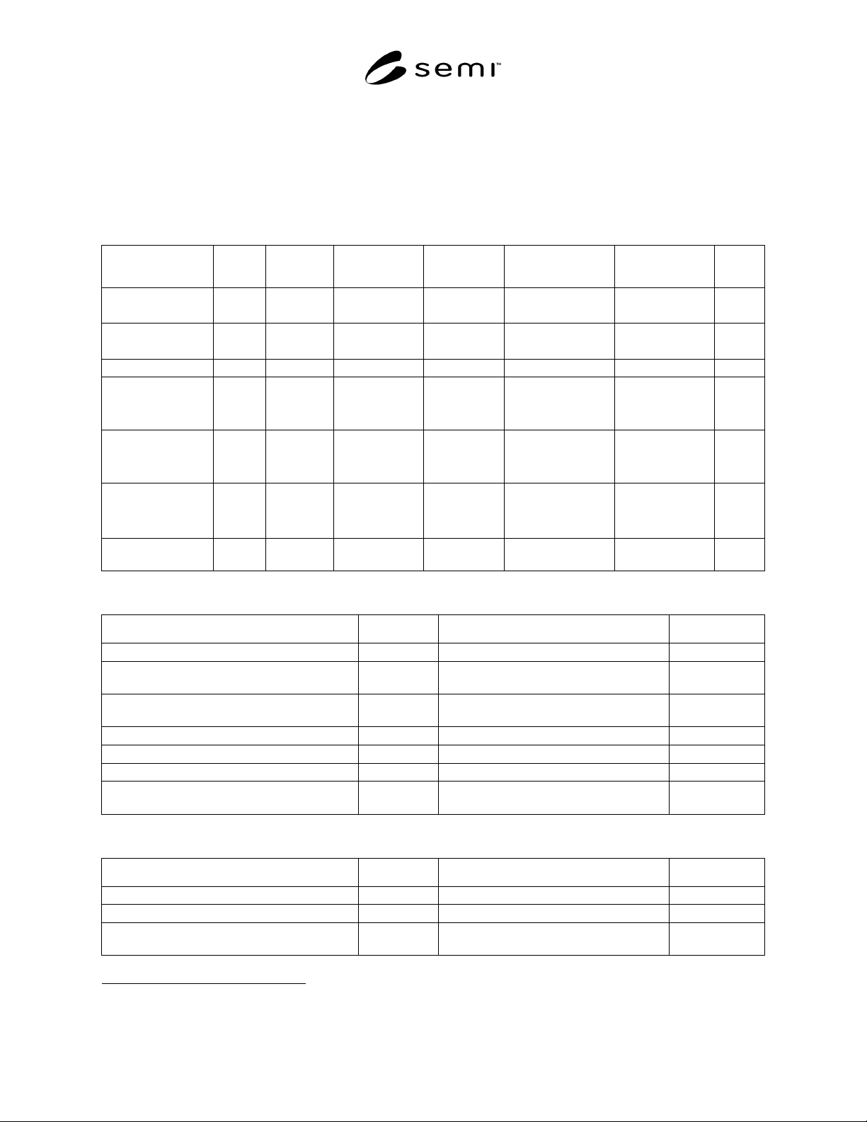
6.4 Table 1 lists the parameters that are considered
important to specify the material quality of SI GaAs
substrates. The level of importance may be adjusted
individually by taking into account the intended use for
implantation or epitaxy. The quoted absolute values
suggest a customary material specification, to be
adopted unless individual considerations warrant other
choices.
6.5 Table 2 lists optional parameters that are important
for specific applications only, hence may or may not be
considered relevant for a particular supplier/purchaser
agreement. For most of these parameters, standard test
methods at present do not exist.
6.6 Table 3 lists other parameters which in general
need not be specified, but are addressed for clarification
and to provide a basis for agreement in the event that a
purchaser desires to include such parameters into a
purchasing specification.
7 Related Documents
7.1 SEMI Standards
SEMI M1 — Specification for Polished
Monocrystalline Silicon Wafers
SEMI M54-0304 © SEMI 2003, 2004 6
SEMI MF523 — Standard Practice for Unaided Visual Inspection of Polished Silicon Wafer Surfaces
SEMI MF1241 — Standard Terminology of Silicon Technology
7.2 Other Docs
5
DIN 50443-2 — Testing of materials for semiconductor technology; recognition of defects and inhomogeneities in
semiconductor single crystals by X-ray topography; III-V-semiconductor compounds
Table 1 Important SI GaAs Material Parameter Specifications and Suggested Standard Values
Parameter Section Wafer
Diameter
Suggested Value Unit Verification
Technique
Standard Test
Method
Section
Carbon
concentration
4.7 n.a. 1 × 10
15
cm
-3
LVM spectroscopy SEMI M30
DIN 50449-1
5.4
Electrical resistivity 4.11 n.a. >1 × 10
7
Ωcm
Hall effect
Capacitive probe
SEMI F76, M39
DIN 50448
5.5
Electron mobility 4.12 n.a. > 6000 cm
2
/Vs Hall effect SEMI F76, M39 5.6
EPD of LEC grown
material
4.13 150 mm
100 mm
76 mm
< 1.5 × 10
5
< 1.0 × 10
5
< 1.0 × 10
5
cm
-2
Structural etching +
light reflection
ASTM F1404,
DIN 50454-1
5.7
EPD of VGF and
VB material
4.13 150 mm
100 mm
76 mm
< 1 ×10
4
< 5 × 10
3
< 5 × 10
3
cm
-2
Structural etching,
light reflection,
microscopy
SEMI M36
DIN 50454-1
5.8
Particles with
diameter
≥ 300 nm
4.17 150 mm
100 mm
76 mm
< 100
< 40
< 20
Wafer with
edge exclusion
Laser scattering none 5.9
Microroughness
(haze)
4.17 n.a. not visible Wafer with
edge exclusion
High intensity
illumination
none 5.18
Table 2 Optional SI GaAs Material Parameter Specifications
Parameter Section Verification Technique Section
Average EL2
0
concentration 4.5 Optical absorption 5.10
Total concentration of impurities acting as
donors
4.6 GDMS, SSMS 5.11
Total concentration of impurities acting as
acceptors
4.7 GDMS, SSMS 5.12
Concentration of boron 4.9 DIN 50449-2, GDMS, SSMS, SIMS, AAS 5.13
Surface concentration of specified contaminants 4.17 TOF-SIMS, TXRF 5.14
Epi-ready qualification including shelf life 4.18 Supplier/purchaser specific 5.15
Surface irregularities (stain, scratches, pits,
orange peel, dimples)
4.17 High intensity illumination or microscopic
inspection (SEMI M15)
5.19
Table 3 Other SI GaAs Material Parameters
Parameter Section Verification Technique Section
Lateral variation of EL2
0
concentration 4.5 Optical absorption topography 5.10
Lateral variation of resistivity 4.11 Transient capacitance, DIN 50448 5.5
Lateral variation of EPD 4.14 Structural etching and light reflection, DIN
50454-1
5.8
5 Available from Deutches Institut für Normung e.V., Beuth Verlag GmbH, Burggrafenstrasse 4-10, D-10787 Berlin, Germany, website:
www.din.de

SEMI M54-0304 © SEMI 2003, 2004 7
NOTICE: SEMI makes no warranties or representations as to the suitability of the standards set forth herein for any
particular application. The determination of the suitability of the standard is solely the responsibility of the user.
Users are cautioned to refer to manufacturer' s instructions, product labels, product data sheets, and other relevant
literature, respecting any materials or equipment mentioned herein. These standards are subject to change without
notice.
By publication of this standard, Semiconductor Equipment and Materials International (SEMI) takes no position
respecting the validity of any patent rights or copyrights asserted in connection with any items mentioned in this
standard. Users of this standard are expressly advised that determination of any such patent rights or copyrights, and
the risk of infringement of such rights are entirely their own responsibility.
Copyright by SEMI® (Semiconductor Equipment and Materials
International), 3081 Zanker Road, San Jose, CA 95134. Reproduction o
f
the contents in whole or in part is forbidden without express written
consent of SEMI.