semi合集-English.pdf - 第3303页
SEMI E130-1104 © SEMI 2003, 2004 17 19.2 Collection Event Table 19.2.1 Table 3 shows eve nts and reports required for the PSE M300 process state transition. Table 4 shows other collection events. Table 3 Collec tion Even…
SEMI E130-1104 © SEMI 2003, 2004 16
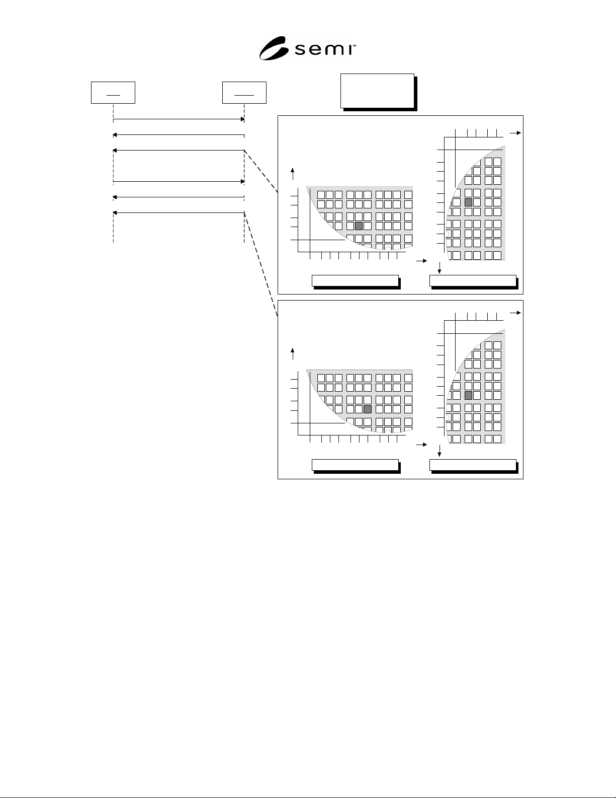
Host Prober
MOVE-ABS(X = 6, Y = 2)
PS: AWAITING COMMAND to MOVING XYZ()
PS: MOVING XYZ to AWAITING COMMAND(X = 6, Y = 2)
Recipe Parameters:
Orientation = 0
OriginLocation = 3
MOVE-ABS(X = 7, Y = 2)
PS: AWAITING COMMAND to MOVING XYZ()
PS: MOVING XYZ to AWAITING COMMAND(X = 7, Y = 2)
1
2
3
4
5
12345678910
X
Y
OrientationOnChuck = 0
12345
1
2
3
4
5
6
7
8
9
10
Y
X
OrientationOnChuck = 90
1
2
3
4
5
12345678910
X
Y
OrientationOnChuck = 0
12345
1
2
3
4
5
6
7
8
9
10
Y
X
OrientationOnChuck = 90
Figure 9
Example OrientationOnChuck
19 Collection Event List
19.1 Requirements
19.1.1 All GEM-required events are required by the PSEM300. Since Processing State Model is required by the
PSEM300, all state transitions are required collection events.
19.1.2
All GEM-required events associated with the Communications, Alarm, and Spooling State Models are
required. This section of the PSEM300 lists only those collection events that are not associated with a change of
state or those requiring specific data variables or reports as defined in the PSEM300.
SEMI E130-1104 © SEMI 2003, 2004 17
19.2 Collection Event Table
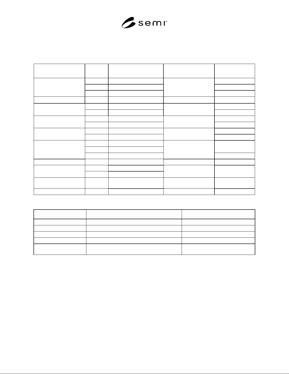
19.2.1 Table 3 shows events and reports required for the PSEM300 process state transition. Table 4 shows other
collection events.
Table 3 Collection Events Required by Process State Transition
Transition Transition
No.
Current State New State Typical Variable Data
1 No state
6 HANDLING MATERIAL
Into IDLE
18 IDLE WITH ALARMS
IDLE
Into IDLE with ALARMS 17 IDLE IDLE with ALARMS Alarm Id
2 IDLE
Into SETTING UP
7 HANDLING MATERIAL
SETTING UP
3 SETTING UP
Into AWAITING LOAD
5 HANDLING MATERIAL
AWAITING LOAD
4 AWAITING LOAD
Into HANDLING
MATERIAL
9 AWAITING COMMAND
HANDLING MATERIAL
8 HANDLING MATERIAL
11 MOVING XYZ
X, Y,Z
Into AWAITING
COMMAND
13 SERVICE TASK
AWAITING COMMAND
X,Y,Z, Task Result
Into MOVING XYZ 10 AWAITING COMMAND MOVING XYZ
12 AWAITING COMMAND
Into SERVICE TASK
14 SERVICE TASK
SERVICE TASK Task Id
Into PROCESSING
BLOCKED
15 PROCESS PROCESS BLOCKED
Conditional 16 PROCESSING BLOCKED PROCESS
Table 4 Additional Collection Events
Event Name Contents Typical Variable Data
CleaningMediaDepleted The cleaning media has been depleted. Cleaning media identifier
InkingMediaDepleted The inking media has been depleted.
ProbeCardRemoved The probe card has been removed from the prober. ProbeCardId
ProbeCardInstalled The probe card has been installed on the prober. ProbeCardId
ControlMapCompleted The prober has completed indexing to each of the sites
identified in the control map.
20 Data Item Variables
20.1 The purpose of this section is to define the list of data item variables required by the PSEM300. Values of
these variables will be available to the host through collection event reports and host status queries.
20.2 Requirements
20.2.1 All generic variable data items defined in GEM are required by all PSEM300 equipment. Any supplier-
defined variables shall be documented in the same format used by this document. The following minimum
information is required:
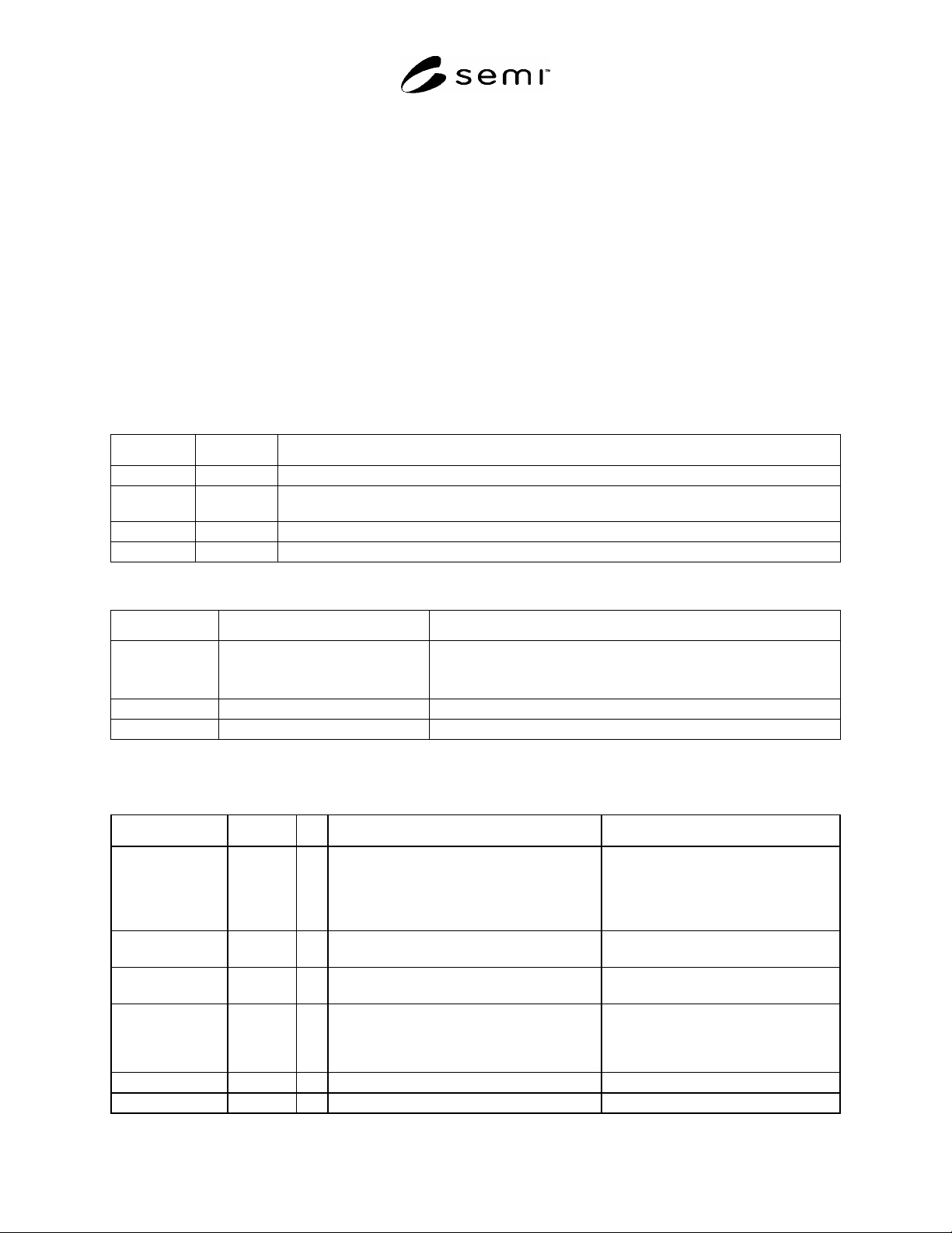
20.3 Data Types
20.3.1 Equipment constants remain in effect until they are overwritten either by manual entry or by a “New
Equipment Constant Send” remote command. Equipment constants have various uses in PSEM300, including the
following:
SEMI E130-1104 © SEMI 2003, 2004 18
1) Equipment offsets that match the performance of several pieces of equipment that would otherwise perform
differently due to inherent manufacturing differences. Examples are home values and motion axis scaling
factors.
2) Setting the configuration of the equipment to allow for different material specifications, equipment options,
material flows, frequency of automatic functions, etc.
3) Managing optional machine features. Examples are constants that tell the system whether optional substrate ID
readers are present and control the configuration and function of these optional subsystems when they are
present.
20.3.2 Status Variables are valid at all times. A status variable may not be changed by the host but may be
changed by the equipment or operator. The value of the status variables may be queried by the host at anytime using
the “Selected Equipment Status Request” remote command (See SEMI E30). Data variables are variables that are
valid only upon the occurrence of specific collection events. An attempt to read a data variable at the wrong time
will not generate an error, but the data reported may not have relevant meaning.
20.3.3 Data Types and Sizes
Table 5 Data Types and Sizes
Type Size Definition
String 0–32767 A string of ASCII characters from zero to “Size” characters in length.
Integer 1,2,4 An integer value that may be represented by “Size” bytes. E.g. If size=2 then the value may be
–32768 to 32767.
Float 4 IEEE single-precision 32-bit floating point type [IEEE 754-1985]
Boolean 1 True or False
Table 6 Composite Data Types
Data Type Definition Comments
DieCoordinate Structure composed of:
XCoordinate
YCoordinate
Structured data used to specify die locations on a substrate
XCoordinate Integer Coordinate in the X direction (column)
YCoordinate Integer Coordinate in the Y direction (row)
20.4 Data Item Variable Table
Table 7 Data Item Variable Table
Variable Name Data Type Size Description Comments
ContactCount Integer 2 The number of times the probe card has come
in contact with a substrate.
This value is reset when the host issues
the SET-PROBE-CARD-ID or RESET-
CONTACT-CNT remote commands.
This data item must be available for the
host to query at all times.
DieXCoordinate Integer 2 The coordinate of the die in the x direction
(column).
Any event associated with the movement
of the chuck requires this variable.
DieYCoordinate Integer 2 The coordinate of the die in the y direction
(row).
Any event associated with the movement
of the chuck requires this variable.
DieZPosition Float 4 The position of the Chuck Z-axis in microns. A
user/supplier defined unit of measure other than
microns is permissible and must be
documented.
Any event associated with the movement
of the chuck requires this variable.
DieZCoordinate Integer 2 The coordinate of the die in the z direction. 0:DOWN, 1:UP
InspectionResult Boolean 1 Result of the last inspection. True:PASS, False:FAIL