semi合集-English.pdf - 第708页
SEMI E92-0302 E © SEMI 1999, 2003 11 APPENDIX 1 APPLICATION NOTES NOTE: The material in this appendix is an official par t of SEMI E92 and was approved b y full letter ballo t procedures on December 3, 1999 b y the Japan…
SEMI E92-0302
E
© SEMI 1999, 2003 10
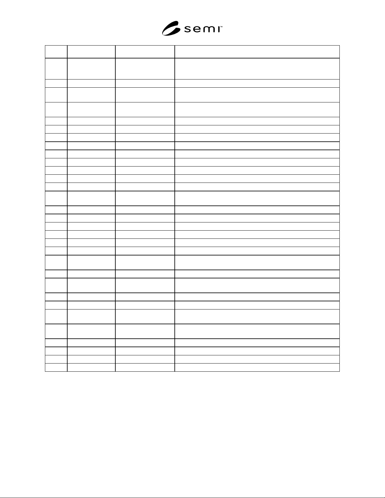
Symbol Value Specified Datum Measured from Feature Measured to
x108 207 ± 1 mm Bilateral datum plane Width of the door seal exclusion volume.
Width of the loader exclusion volume.
Width of the loader bottom flange exclusion volume. (Inside)
x109 235 mm minimum Bilateral datum plane Width of the loader bottom flange exclusion volume. (Outside)
y101 170 ± 2 mm Docked Facial datum
plane
BOLTS/Light plane. Seal surface on equipment.
y102 80 mm minimum BOLTS/Light plane Encroachment of equipment on the permanent reserved space and on
the reserved space when the door is opening or closing.
y103 3 mm minimum BOLTS/Light plane Encroachment of equipment.
y104 200 + 0/-10 mm Facial datum plane Rear edge of bottom interface plane.
y105 220 + 0/-10 mm Facial datum plane Front edge of bottom interface plane.
y106 180 ± 0.05 mm Facial datum plane Positioning pin location.
y107 100 ± 0.3 mm Facial datum plane Front locking screw location.
y108 100 ± 0.3 mm Facial datum plane Rear locking screw location.
y109 110 + 0/-5 mm Facial datum plane Rear edge of control connection area.
y110 [E63] Facial datum plane Docked-facial datum plane.
y111 220 ± 2 mm Facial datum plane Front end of the loader exclusion volume.
y112 31 mm minimum BOLTS/Light plane Encroachment of equipment on the reserved space when the door is
closed.
y113 ± 0.5 mm - Cycle-to-cycle repeatability of y101.
y114 ± 1 mm - Flatness of seal zone.
y115 220 mm minimum Facial datum plane Front face of the loader bottom flange exclusion volume.
y116 200 mm minimum Facial datum plane Rear face of the loader bottom flange exclusion volume.
z101 402 ± 1 mm Horizontal datum plane Outside edge of seal zone on top.
z102 478 ± 1 mm Horizontal datum plane Outside edge of seal zone on bottom.
z103 394 mm minimum Horizontal datum plane Encroachment of equipment on the top of the permanent reserved
space inside the equipment.
z104 395 ± 1 mm Horizontal datum plane Top edge of hole opening and inside edge of seal zone.
z105 470 mm minimum Horizontal datum plane Encroachment of equipment on the bottom of the permanent reserved
space inside the equipment.
z106 471 ± 1 mm Horizontal datum plane Bottom edge of hole opening and inside edge of seal zone.
z107 480 ± 1 mm Horizontal datum plane Height of the bottom interface planes.
z108 45 ± 2 mm Horizontal datum plane Encroachment of equipment on the top of the permanent reserved
space inside the equipment.
z109 402 ± 2 mm Horizontal datum plane Encroachment of equipment on the top of the box opener/ loader
between the BOLTS/Light plane and the SEMI E15.1_D1 plane.
z110 10 ± 1 mm Bottom end of z107 locating pins height.
z111 45 ± 2 mm Horizontal datum plane Panel Interface Height.
z112 15 mm minimum Bottom end of z107 Docking space to bottom interface plane during maintenance.
z113 30 mm minimum Bottom end of z107 Height of loader bottom flange exclusion volume.

SEMI E92-0302
E
© SEMI 1999, 2003 11
APPENDIX 1
APPLICATION NOTES
NOTE: The material in this appendix is an official part of SEMI E92 and was approved by full letter ballot procedures on
December 3, 1999 by the Japanese Regional Standards Committee.
A1-1 NOTICE: Usage of Loader Locating Pins
A1-1.1 In order to provide quick interchangeability
with accurate repeatability, it is recommended to use V
shaped groove to couple with the positioning pin and
use flat plane to couple with the anti-rotation pin as
shown in Figure 4.
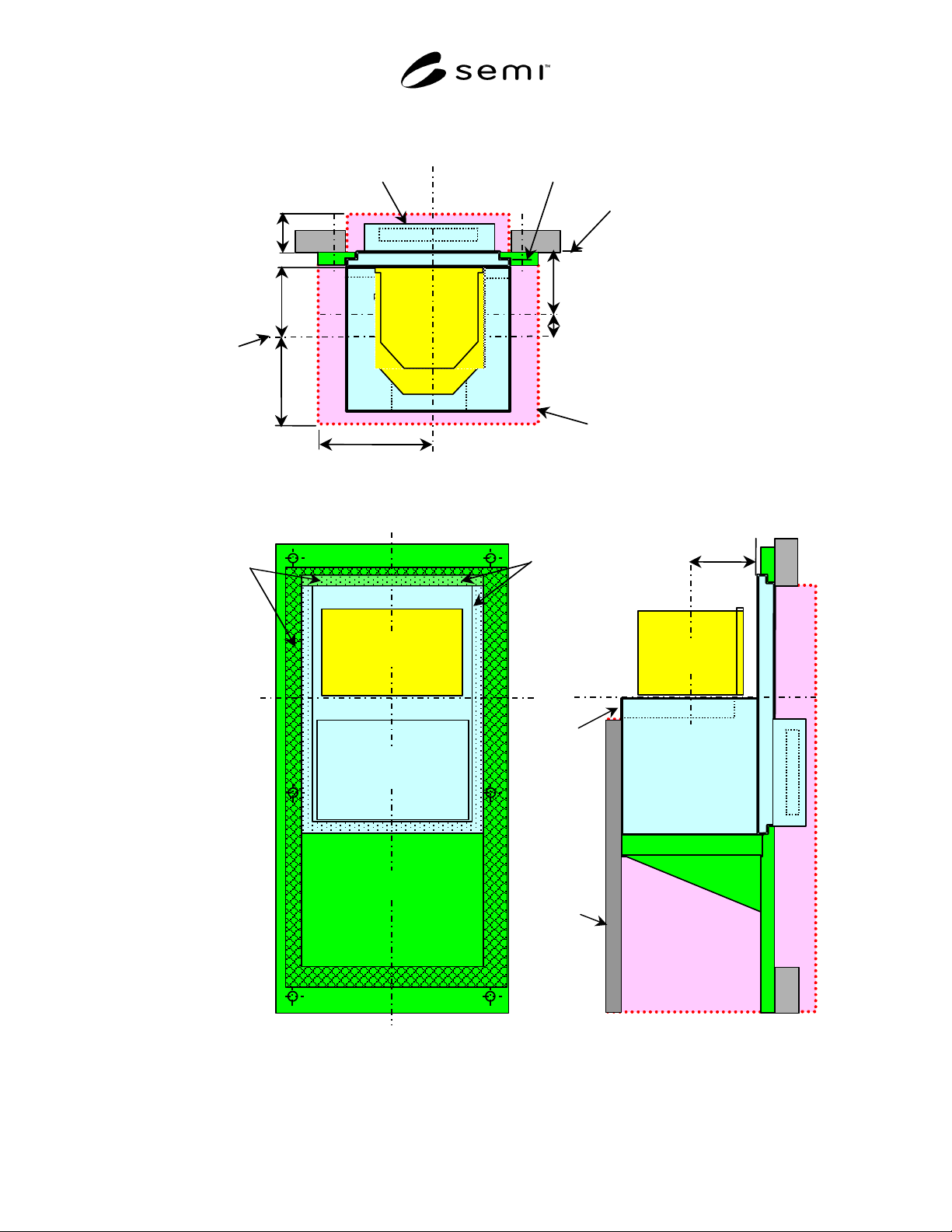
A1-2 NOTICE: BOLTS/Light Shelf
A1-2.1 BOLTS/Light Shelf may be used in order to
keep compatibility with BOLTS/M interface. In this
case, BOLTS/M interface provides backward compati-
bility of equipment interface and BOLTS/Light inter-
face provides standardized precise quick attachment/
detachment interface. BOLTS/Light shelf is shown in
Figure A-1.
A1-3 NOTICE: Box Opener/Loader Compati-
bility
A1-3.1 It is recommended that equipment suppliers
design their process equipment to be capable of
accepting box opener/loaders that interface with either a
BOLTS/M interface or a BOLTS/Light interface. This
standard has been structured to make the BOLTS/Light
interface a component capable of being attached to a
BOLTS/M interface. (It is not physically feasible to
make the BOLTS/M interface an optional component
capable of being attached to a BOLTS/Light interface).
A1-3.2 If an equipment supplier provides a BOLTS/M
interface, their process equipment can be modularly
configured to interface with either type of box/opener
loader. This type of approach allows “two-way
compatibility”:
• Process equipment with a BOLTS/M interface can
attach a BOLTS/Light interface. This enables the
process equipment to now accept a box
opener/loader with a BOLTS/Light interface.
• Process equipment with a BOLTS/Light interface
can remove the BOLTS/Light interface to expose a
BOLTS/M interface. This enables the process
equipment to now accept a box opener/loader with
a BOLTS/M interface.
Equipment suppliers may provide only a BOLTS/Light
interface at their discretion. However, it should be
understood that process equipment designed in this
manner can not be modularly configured to accept a
box/opener loader with a BOLTS/M interface.
A1-4 NOTICE: Docking Stroke Variation for
Backward Compatibility
A1-4.1 In order to provide the “Backward compatibil-
ity” requested in I300I/J300 GJG
1
, vendors who want to
use this standard to put BOLTS/Light unit in their exist-
ing BOLTS/M compliant loadport unit may vary dock-
ing stroke as their option to accommodate their existing
designs. The unit that has a different docking stroke is
no more a BOLTS/Light-Full-Compliant unit, but could
be called as BOLTS/Light-Quasi-Compatible unit.
A1-5 NOTICE: Sliding Mechanism
A1-5.1 Actual design of the sliding mechanism is left
to the box opener/loader and/or equipment designer.
The equipment provides bottom interface planes as the
loading slider areas.
A1-5.1.1 This implies several types of bottom interface
planes are acceptable by the equipment; e.g., roller
guided, plastic material based, etc.
A1-6 NOTICE: Maintenance Cart
A1-6.1 If the box opener/loader is too heavy to
attach/detach manually by maintainer, this standard
provides for the possibility/capability of cart-based
maintenance.
A1-6.2 The cart may use the same cart to equipment
docking mechanism as the cart for FOUP delivery.
A1-6.3 The maintenance cart may also use a
connection with the bottom interface planes that are
defined in this standard. Specification of how to make
the carts is outside the scope of this standard.
A1-7 NOTICE: Finger Pinch Sensor
A1-7.1 This document does not define or specify a fin-
ger pinch sensor. Considering finger pinching with
edges, the following approach may be recommended.
• Finger pinching with edges is more serious than it
is with flat surfaces. So, it is recommended not to
place the box flange seal in a narrow tunnel
structure which have sharp edges but place it on a
flat surface (or in a dimple that has chamfered
edges).
1 I300I/J300 GJG — I300I/J300 Global Joint Guidance for 300 mm
Semiconductor Factories. SEMATECH, 2706 Montopolis Drive,
Austin, TX, 78741. http://www.sematech.org
SEMI E92-0302
E
© SEMI 1999, 2003 12
BOLTS/Light
SEMI
E15.1-D1
FOUP
HDP
FDP
BOLTS/Light
Shelf
BOLTS/M
SEMI E15.1-D
SEMI E15.1-
D1
Docking
Stroke
BOLTS/M
BOLTS/M
BOLTS/Light Plane
FDP
BOLTS/M
BDP
BOLTS/Light
BOLTS/M Plane
FOUP
BOLTS/Light
BOLTS/Light
Shelf
BDP
HDP
BOLTS/M Seal
zone
BOLTS/Light
Seal zone
(on the back side)
Top View
Rear View
Side View
Equipment
panel
Forklifts
Exclusion
volume
Figure A-1
Usage of BOLTS Shelf (Adopter)