semi合集-English.pdf - 第259页
SEMI E43-0301 © SEMI 1995 , 2001 7 A) Connec t meter dir ectl y to charged plate groun d refer ence. B) Meter approxim ately 2.54 cm and parallel t o charg e plate. C) Meter re ading sh ould be within 5% of volt age appl…
SEMI E43-0301 © SEMI 1995, 2001 6
10.3 Demonstrating Ability to Measure Example Item(s) Acceptably — The certifier will have charged/uncharged
example(s) of items/objects for measurement of static field(s) by certifyee(s) a minimum of two times per Section 9;
record values per Section 11.
10.4 Certifying — Readings obtained per Section 10.2 shall be within 12% of expected values and methodology of
obtaining readings shall be acceptable per certifier observation(s). A permanent record of certification is realized by
certifyee when certifier signs record sheet(s) for file in personnel records and/or when certifier issues a certificate.
Refer to Section R1-3.
11 Documentation
11.1 Meter calibration check(s), benchmark or laboratory measurements, items/areas surveys, and/or any other
electrostatic field measurements should be recorded in permanent records. Recorded are initial reading,
second/validation reading, and any subsequent readings taken to acceptable range/bound levels observed. Record
sheet(s) should show meter used, area (name), location, date, and items listed opposite readings, name of person
who took readings, and space for comments.
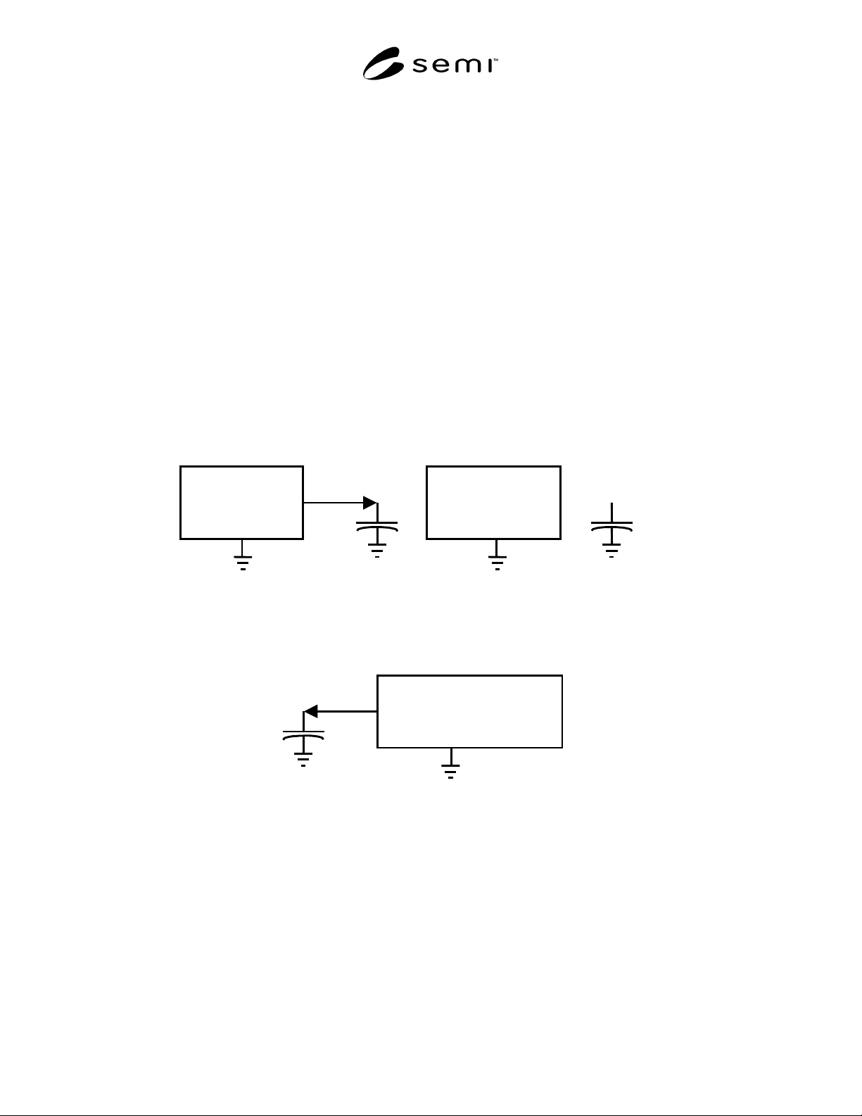
Charging
Source
STEP 1
Charge
Capacitor
Charging
Source
STEP 2
Disconnect
Charging
Source from
Capacitor
Coulombmeter
STEP 3
Connect
Coulombmeter
to Capacitor
Figure 1
Verifying Performance of the Coulombmeter
SEMI E43-0301 © SEMI 1995, 20017
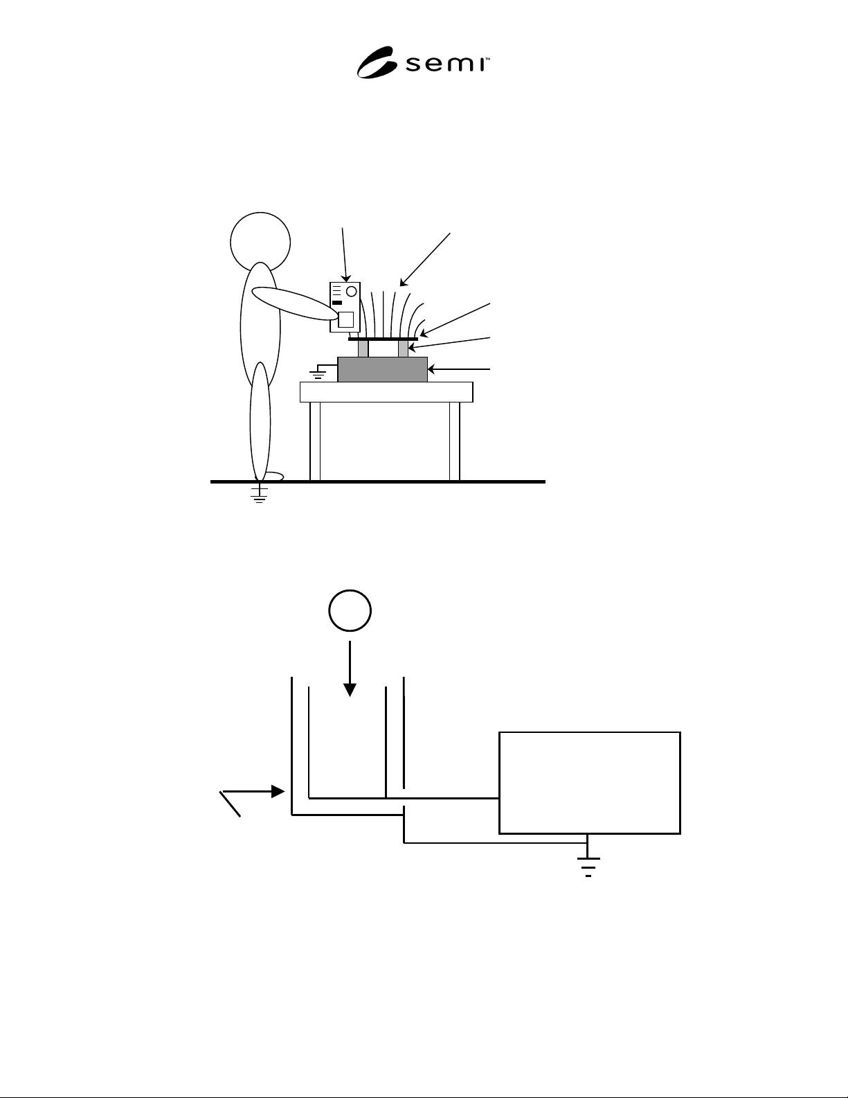
A) Connect meter directly to charged plate ground reference.
B) Meter approximately 2.54 cm and parallel to charge plate.
C) Meter reading should be within 5% of voltage applied to plate.
D) Assure that both the meter and the operator are properly grounded.
Meter
Field emanating from charge plate
Plate
Ground Plane
Insulators
Charged Plate monitor
or power supply
Figure 2
Fieldmeter and Voltmeter Verification Check
Coulombmeter
Place object into
Faraday
enclosure.
Faraday Enclosure
Figure 3
Measurement With a Coulombmeter and Faraday Enclosure
SEMI E43-0301 © SEMI 1995, 2001 8
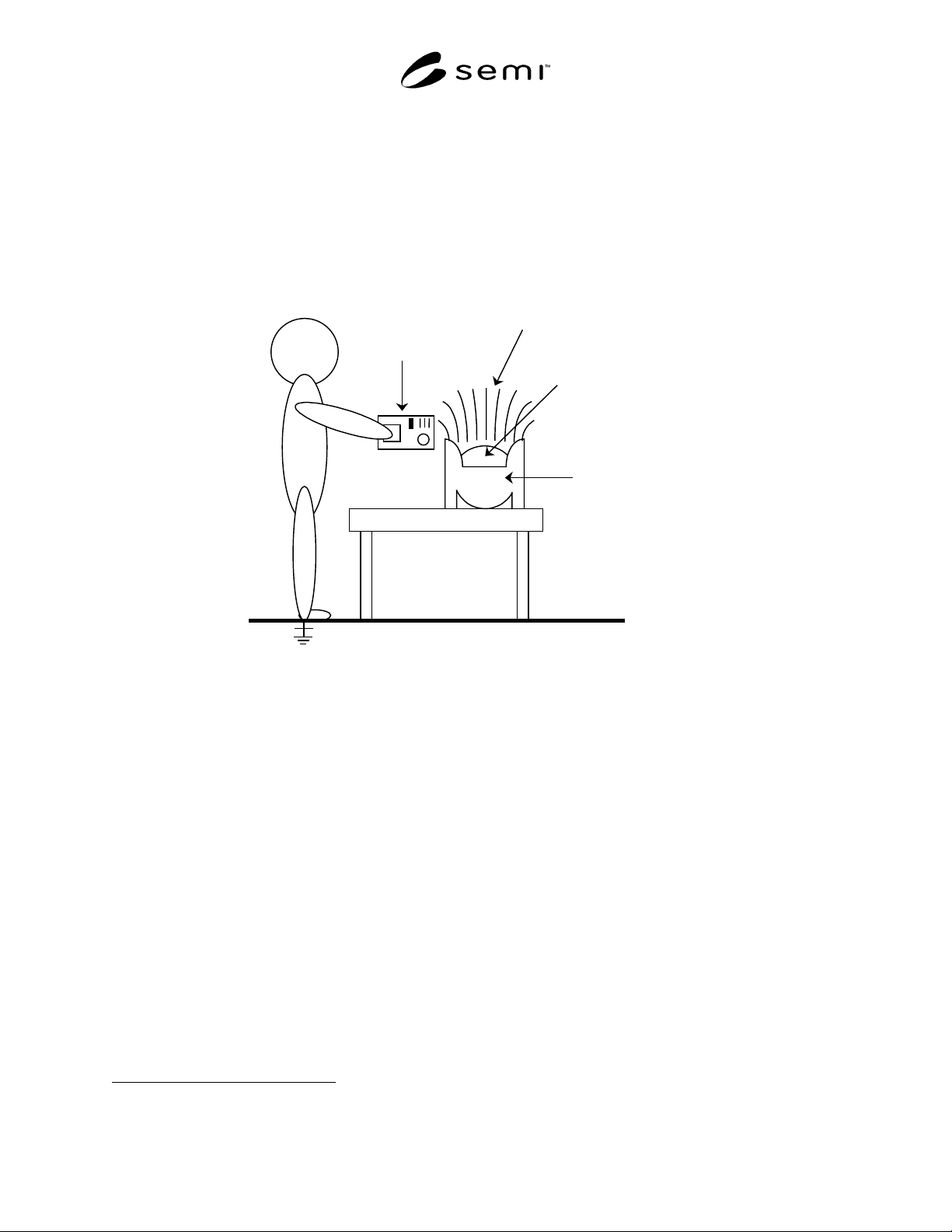
A) Make sure meter is properly grounded according to manufacturer's
instructions.
B) Scan approximately 2.54 cm along both sides and ends of carrier.
C) Scan approximately 2.54 cm length of carrier and top-center of
wafers with meter.
D) Note high-low values for B) & C).
E) Assure that the operator is properly grounded.
Meter
Field emanating from carrier of charge
semiconductor wafers.
Wafers
Ground Plane
Carrier
Figure 4
Example of a Survey of a Carrier of Semiconductor Wafers
12 Related Documents
NOTE 2: These documents are for information only; in the
case of conflict, this document takes precedence. Also read/be
aware of appendices to this document before use.
12.1 ESD Association Standards
1
ANSI EOS/ESD S3.1: Ionization. Test methods and
procedures for evaluating and selecting air-ionization
equipment and systems are provided in this standard,
which establishes measurement techniques to determine
ion balance and charge-neutralization time for ionizers.
ESD STM4.2: Worksurfaces — Charge Dissipation
Characteristics. This standard test method prescribes a
procedure for measuring the electrostatic-charge-
dissipation characteristics or work surfaces used for
ESD control.
1 ESD Association, 7900 Turin Rd., Bldg. 3, Suite 2, Rome, NY
13440-2069, website: www.esda.org
ESD STM5.1: ESD Sensitivity Testing — Human Body
Model. This standard test methods defines procedures
for testing, evaluating, and classifying the ESD
sensitivity of components to the defined Human Body
Model (HBM).
ESD S5.2: ESD Sensitivity Testing — Machine Model.
This standard established a test procedure for
evaluating the ESD sensitivity of components to a
defined Machine Model, and outlines a system whereby
the sensitivity of such components may be classified.
ESD STM5.3.1: ESD Sensitivity Testing — Charged
Device Model. This standard is a test method for
evaluating active and passive components’ ESD
sensitivity to a defined Charged Device Model.
ANSI/ESD S20.20: ESD Control Program. This
standard specifies the requirements that must be
satisfied in designing, establishing, implementing, and
maintaining ESD control programs for ESD-sensitive