semi合集-English.pdf - 第4425页
SEMI F100-0705 © SEMI 2005 1 SEMI F100-0705 COMPLIANCE TEST METHOD FOR MI NIMUM FLOW COEFFICIENT OF DIAPHRAGM VALVE FOR METRIC PFA TUBE This test method was technically approved by the Global Liquid Chemicals Com mittee.…
SEMI F99-0705 © SEMI 2005 2
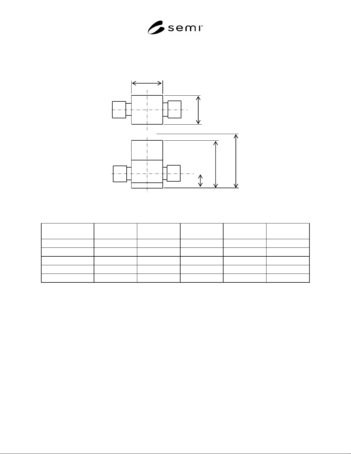
5.2 Port Height Dimensions — The height (A) indicated in Figure 1 and the values for different tube sizes are
specified in Table 1.
5.3 Body Dimensions — The length (D) and width (E) of the body indicated in Figure 1 and the values for different
tube sizes are specified in Table 1.
C
(with flow control)
B
A
E
D
D
Figure 1
Top View of A Typical Diaphragm Valve
Table 1 Dimensional Specifications
Tube Size (mm) (OD /
ID)*
A (mm) B (mm) C (mm) D (mm) E (mm)
25/22 35–40 MAX 145 MAX 175 MAX 62 MAX 62
19/16 25–30 MAX 120 MAX 150 MAX 60 MAX 60
12/10 20–30 MAX 95 MAX 115 MAX 36 MAX 40
10/8 20–25 MAX 95 MAX 115 MAX 36 MAX 40
6/4 15–25 MAX 80 MAX 100 MAX 35 MAX 35
#1
OD and ID are the outside diameter and inside diameter of the tube respectively.
#2
As seen above, dimensions of A are specified by the range, and dimensions from B to E are specified as maximum dimensions that are to be
considered as targets.
6 Measurements
6.1 The mounting base must be conditioned for a minimum of one hour in an air environment of 23 3ºC
(73.4 5.4ºF) prior to measuring the dimensions.
NOTICE: SEMI makes no warranties or representations as to the suitability of the standards set forth herein for any
particular application. The determination of the suitability of the standard is solely the responsibility of the user.
Users are cautioned to refer to manufacturer's instructions, product labels, product data sheets, and other relevant
literature, respecting any materials or equipment mentioned herein. These standards are subject to change without
notice.
By publication of this standard, Semiconductor Equipment and Materials International (SEMI) takes no position
respecting the validity of any patent rights or copyrights asserted in connection with any items mentioned in this
standard. Users of this standard are expressly advised that determination of any such patent rights or copyrights, and
the risk of infringement of such rights are entirely their own responsibility.
Copyright by SEMI® (Semiconductor Equipment and Materials
International), 3081 Zanker Road, San Jose, CA 95134. Reproduction of
the contents in whole or in part is forbidden without express written
consent of SEMI.

SEMI F100-0705 © SEMI 2005 1
SEMI F100-0705
COMPLIANCE TEST METHOD FOR MINIMUM FLOW COEFFICIENT OF
DIAPHRAGM VALVE FOR METRIC PFA TUBE
This test method was technically approved by the Global Liquid Chemicals Committee. This edition was
approved for publication by the global Audits and Reviews Subcommittee on March 11, 2005. It was
available at www.semi.org in June 2005 and on CD-ROM in July 2005.
1 Purpose
1.1 This compliance test method presents that the verification of the compatibility of each diaphragm valves for
Metric PFA tube simply.
1.2 This document specifies the relative orifice that gives the minimum flow coefficient for diaphragm valve for
Metric PFA tube.
1.3 This compliance test method describes how to verify the flow coefficient of the diaphragm valve by comparing
with the relative orifice.
2 Scope
2.1 This Specification addresses a capacity of diaphragm valves used with metric PFA tubes.
2.2 These diaphragm valves are used in chemical distribution systems for semiconductor and flat panel display
manufacturing.
2.3 The valves are made from materials such as PTFE or PFA, which have high corrosion resistance and low
contamination contribution to the fluid.
2.4 The valves withstand up to 0.2 megapascals (MPa) [29 pounds per square inch (psi)] backpressure.
2.5 Fully open to fully shut switch over is the objective of the shut-off valve.
NOTICE: This standard does not purport to address safety issues, if any, associated with its use. It is the
responsibility of the users of this standard to establish appropriate safety and health practices and determine the
applicability of regulatory or other limitations prior to use.
3 Terminology
3.1 Abbreviations and Acronyms
3.1.1 PFA — Perfluroalkoxy
3.1.2 PTFE — Polytetrafluoroethylene
3.1.3 P1 — Gauge pressure at upstream pressure tap, kPa
3.1.4 Q — Volumetric flow rate
3.2 Definitions
3.2.1 back pressure — a maximum allowable pressure applied to outlet of a diaphragm valve.
3.2.2 liquid chemicals — acid, alkali, organic solvent, and pure water used for wet stations; resists and developers
used for track system; and other chemicals used for process or maintenance (such as slurry of CMP) of equipment or
facilities.
4 Test Fluids
4.1 Incompressible (Liquid) Fluid — Water is standard liquid test fluid.
SEMI F100-0705 © SEMI 2005 2
5 Test Setup
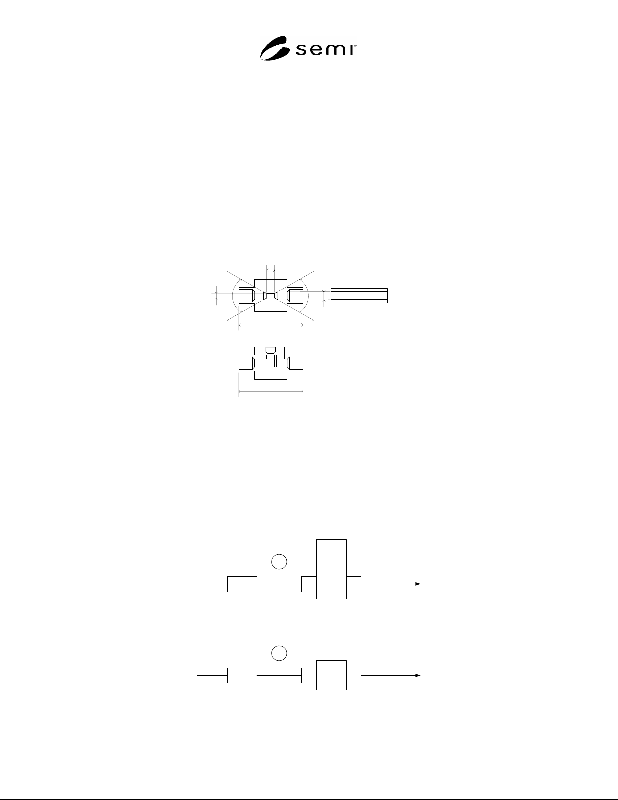
5.1 Standard Orifice
5.1.1 Orifice Diameter (A)
On the basis of 50% of the inner diameter of PFA tube connection. See Figure 1.
2.0[mm] orifice (6-4[mm] tube)
4.0[mm] orifice (10-8[mm] tube)
5.0[mm] orifice (12-10[mm] tube)
8.0[mm] orifice (19-16[mm] tube)
11.0[mm] orifice (25-22[mm] tube)
M e tric PFA TubeB
C
D
E
S ta n d a rd O rifice
Diaphragm V alve
A
FF
Figure 1
Inside View of
Standard Orifice
5.1.2 Orifice Diameter Tolerance
Tolerance: +0.2, 0 [mm]
5.1.3 Orifice Length (B) should be less than inner tube diameter, i.e., B A.
5.1.4 Dimensions (D) should be determined in accordance with the test valve port connection, i.e., D E.
5.1.5 Dimension (F) should be equal to or less than a 90 degree angle.
5.2 Test Circuit
Va l v e
flow meter
pressure sensor
Standard Orifice
flow meter
pressure sensor
Figure 2
Test Circuit