semi合集-English.pdf - 第3783页
SEMI F7-92 © SEMI 19 92, 1999 3 14.1 Date tested . 14.2 Op erator and test facility. 14.3 Descrip tion of items tested, including: Tubing manu fact urer , O.D., wall thic kness, par t number, and m aterial t ype. Fitti…
SEMI F7-92 © SEMI 1992, 1999 2
7. Description of Test Equipment
7.1 A test apparatus capable of securing the test
specimen while accurately providing a uniform rate
of pull to the specimen. The test instrument shall
have the capability of recording the maximum tensile
force applied to the test specimen.
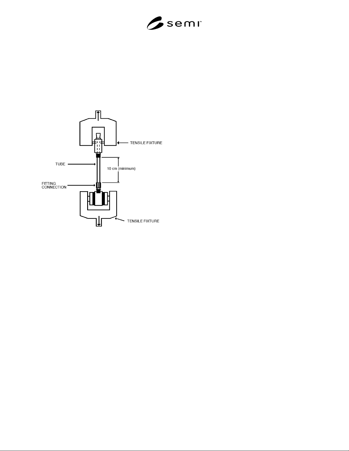
7.2 See Figure 1 for basic tensile test apparatus.
Figure 1
Basic Tensile Test Apparatus
8. Safety Precautions
WARNING: This test method will subject test
specimens to conditions that may exceed the
normal performance rating of the products
under evaluation. Adequate precautions
must be taken to prevent injury to the person
conducting the test.
9. Test Specimens and Conditioning
9.1 Sample Size A minimum of three specimens
shall be tested.
9.2 Specimen Size The specimen length shall be
no less than 10 cm (4 in) between the tensile fixture
and the tube end of the fitting connection.
9.3 Specimen Surface All surfaces of the
specimens shall be free of visible flaws, scratches, or
other imperfections, unless typically found on a
representative sample of the product.
9.4 Specimen Conditioning All specimens must
be conditioned for a minimum of one hour in an air
environment of 23° ± 2.8°C (73° ± 5°F) prior to
being subjected to tensile forces.
10. Calibration
10.1 Calibrate the tensile test equipment's rate of
pull to 2.5 cm (1 in) per minute, ± 5%.
10.2 Calibrate the tensile force instrument to ± 2%
full scale.
11. Test Procedure
11.1 Assemble a test fitting connection, per
manufacturer's specification, to one end of the tube.
(See 9.2.)
11.2 Install the fitting connection to the tensile
fixture (see Figure 1) in a manner that prevents
distortion of the connection.
11.3 Secure the open end of the tube to the tensile
fixture, leaving a minimum of 10 cm (4 in) of
exposed tube.
11.4 Begin pulling the test specimen at a rate of 2.5
cm (1 in) per minute.
11.5 Continue applying tensile force until the tube
pulls through the fitting connection or until tearing of
the tube occurs.
11.5.1 If the tube releases from the tensile fixture,
the data from that specimen must be disregarded and
an additional specimen tested.
11.6 Record on test data sheet (see Appendix 1 for a
sample) the mode of failure and the maximum tensile
force applied, in Newtons (lbs).
12. Calculations
12.1 Calculate the average "maximum tensile force"
and record.
12.2 Calculate the standard deviation of "maximum
tensile force" and record.
13. Data Accuracy
13.1 Tensile Force Newtons: ± 2%.
14. Test Data Sheet
The test data sheet shall include the following
information:
SEMI F7-92 © SEMI 1992, 19993
14.1 Date tested.
14.2 Operator and test facility.
14.3 Description of items tested, including:
Tubing
manufacturer, O.D., wall thickness, part
number, and material type.
Fitting
manufacturer, type, size, part number, and
material type.
14.4 Maximum tensile force for each specimen.
14.5 Average and standard deviation of maximum
tensile forces.
14.6 Mode of failure for each specimen.
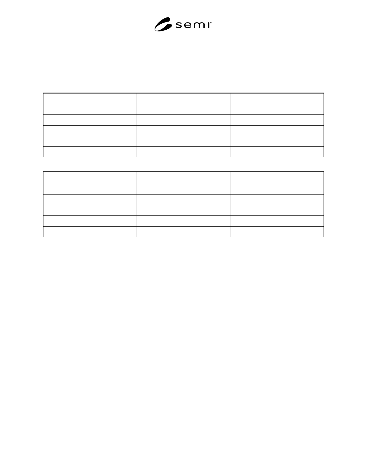
NOTE: A sample test data sheet is provided as
Appendix 1.
SEMI F7-92 © SEMI 1992, 1999 4
APPENDIX 1
SAMPLE TEST DATA SHEET
NOTE: This related information is not an official part of this SEMI test method and is not intended to modify or
supercede the official test method. It has been derived from industry specifications. Publication was authorized by
full letter ballot procedures. Determination of the suitability of the material is solely the responsibility of the user.
Test Date: Operator: Test Facility:
Tube Manufacturer: Fitting Manufacturer:
Tube O.D.: Fitting Type:
Tube Wall Thickness: Fitting Size:
Tube P/N: Fitting P/N:
Tube Material: Fitting Material:
Tensile Force Newtons
Sample Maximum Tensile Force Mode of Failure
1
2
3
Average =
Standard Deviation =
NOTICE: These standards do not purport to address safety issues, if any, associated with their use. It is the
responsibility of the user of these standards to establish appropriate safety and health practices and determine the
applicability of regulatory limitations prior to use. SEMI makes no warranties or representations as to the suitability
of the standards set forth herein for any particular application. The determination of the suitability of the standard is
solely the responsibility of the user. Users are cautioned to refer to manufacturer's instructions, product labels,
product data sheets, and other relevant literature respecting any materials mentioned herein. These standards are
subject to change without notice.
The user's attention is called to the possibility that compliance with this standard may require use of copyrighted
material or of an invention covered by patent rights. By publication of this standard, SEMI takes no position
respecting the validity of any patent rights or copyrights asserted in connection with any item mentioned in this
standard. Users of this standard are expressly advised that determination of any such patent rights or copyrights, and
the risk of infringement of such rights, are entirely their own responsibility.
Copyright by SEMI® (Semiconductor Equipment and Materials
International), 3081 Zanker Road, San Jose, CA 95134. Reproduction o
f
the contents in whole or in part is forbidden without express written
consent of SEMI.