semi合集-English.pdf - 第7627页
SEMI T3-0302 © SEMI 1995, 2002 9 8.2.2 P lace one label on the center of the rear surf ace of the FOSB with the long axis of th e label perpendicular to the FOSB base (see Figu re 8a). 8.2.3 Place the other, identical, l…
SEMI T3-0302 © SEMI 1995, 2002 8
6.3.10.1 The initial six characters are a non-printed
message header. The next 570 characters are restricted
to the Code 39 Character Set (see 6.1.6) using the six-
bit EDIFACT encodation scheme described in Annexe
J3 of ISO/IEC 16022. The remaining 105 message
characters may be any character in the EDIFACT
Encodation Character Set, including unprinted ones.
These 105 characters are available for encrypted or
unencrypted information, as negotiated between
supplier and customer.
6.3.11 Print Quality — To assure reading efficiency, a
minimum contrast of 30% is required between the
reflectance value of a dot and the surrounding label
surface. Various densitometers can provide such
measurements nondestructively.
7 Label Types, Label Dimensions, and
Placement of Data Fields on Labels
7.1 Label Types (see Figure 5 for examples)
7.1.1 Type 1 — Company Field + Data Matrix Field
with hri fields
7.1.2 Type 2 — Company Field + Bar Code Field with
hri fields
7.1.3 Type 3 — Company Field + Data Matrix Field +
Bar Code Field with hri fields. Two of this type of
label are required for use on 300 mm FOSBs.
NOTE 6: The space reserved on the FOSB rear surface
accepts labels as large as 120 mm by 120 mm. This permits
the use of labels wider than is specified in this standard. Such
labels may contain additional information as arranged by
agreement between customer and supplier.
7.1.4 Type 4 — Company Field + Data Matrix Field1 +
Bar Code Field with hri fields + Data Matrix Field2
with hri fields
7.1.5 Type 5 — Company Field + two Data Matrix
Fields, both with hri fields
7.2 Each label shall contain an area containing
Company Information and one or more areas containing
bar codes, data matrix codes, and related human-
readable information.
7.2.1 The Company Information area may contain
supplier-related information in human-readable alpha-
numeric format and other information as agreed to
between customer and supplier.
7.2.2 The other fields that contain bar code, human-
readable, and two-dimensional matrix code data fields,
may be arranged as indicated in the examples shown in
Figure 5.
7.2.3 The human-readable (hri) data fields can be
placed either above or below their associated bar code
data fields. The examples in Figure 5 show the
configuration with the hri fields above the bar code data
fields.
7.3 Approximate overall dimensions of the five label
types shown in Figure 5 are tabulated in Table 6.
7.4 Dimensions of individual fields, label height, and
label length for a type 4 label are given in Table 5 and
Figure 6. Label types 4 and 5 may use perforated label
material so that the sections may be separated after
printing.
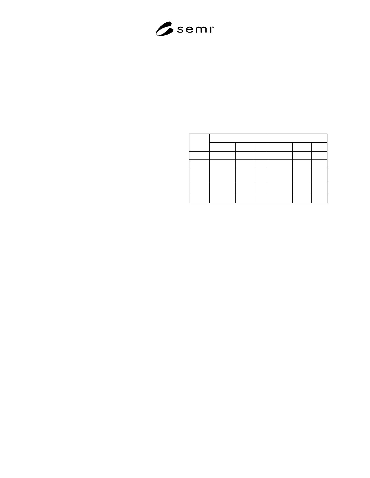
Table 6 Overall Dimensions of Box Labels
Length Width
Label
Type
Symbol mm in. Symbol mm in.
1 F+ S 54.2 2.1 A 25.0 1.0
2 F+ L 97.0 3.8 A 25.0 1.0
3 P=F+ T+
L
119.
0
4.7 A 25.0 1.0
4 P+ S 149.
0
5.9 A 25.0 1.0
5 F+ 2S 84.2 3.3 A 25.0 1.0
NOTE 1: For meaning of the symbols, see Table 5.
8 Label Locations on Wafer Box
8.1 For boxes containing wafers from 100 to 200 mm
in diameter, the following recommendations apply.
8.1.1 It is recommended that label type 4 or label type
5 be used for these boxes. These label types may be
printed on perforated label material so that the sections
may be separated after printing.
8.1.2 The recommended location for the larger label is
the center (both vertically and horizontally) of the side
of the cover of the wafer box facing the operator with
the bar end to the left and the wall end to the right (see
Figure 7). Alternatively, this label may be placed in the
center of the same side of the base of the wafer box.
8.1.3 The recommended location for the smaller label
is the center (both vertically and horizontally) of the
wall end of the base of the wafer box (see Figure 7).
Alternatively, this label may be placed at the center of
the wall end of the cover of the wafer box.
8.1.4 It is recommended that the wafer box cover and
the wafer box base each contain a label, so that each
will have a label after they have been separated.
However, in some cases, space limitations may require
that both labels be placed on the same part of the wafer
box.
8.2 For FOSBs containing 300 mm wafers, the
following requirements apply.
8.2.1 Use two identical Type 3 labels.
SEMI T3-0302 © SEMI 1995, 2002 9
8.2.2 Place one label on the center of the rear surface of the FOSB with the long axis of the label perpendicular to
the FOSB base (see Figure 8a).
8.2.3 Place the other, identical, label on the outer wrap bag, which is specified in SEMI M31, at the center of the
side adjacent to the FOSB door (see Figure 8b).
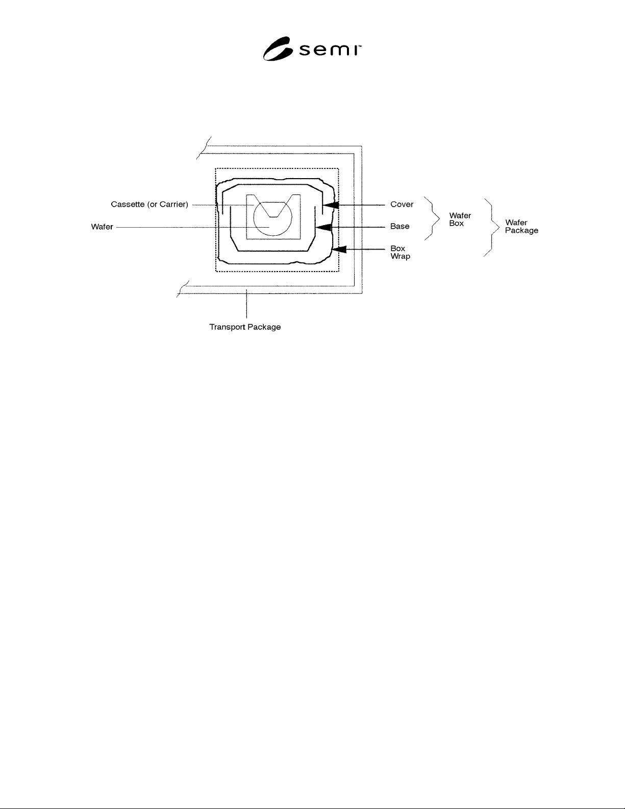
NOTE 1: This specification covers only labels for the wafer package, including the wafer boxes and the wafer box wrap; labels
for transport packages are specified in EAI 556-B.
Figure 1
Wafer Box, Wafer Package and Transport Package
SEMI T3-0302 © SEMI 1995, 2002 10
P 98765432+2P 93+20P 96+21P 06+12P 4+22P 25
CUSTOMER PRODUCT ID
DATA IDENTIFIER
CUSTOMER
PART # REV.
DATA IDENTIFIER
CUSTOMER
SPEC #
DATA IDENTIFIER
CUSTOMER
SPEC # REV.
DATA IDENTIFIER
CUSTOMER
DRAWING #
DATA IDENTIFIER
CUSTOMER
DRAWING # REV.
DATA IDENTIFIER
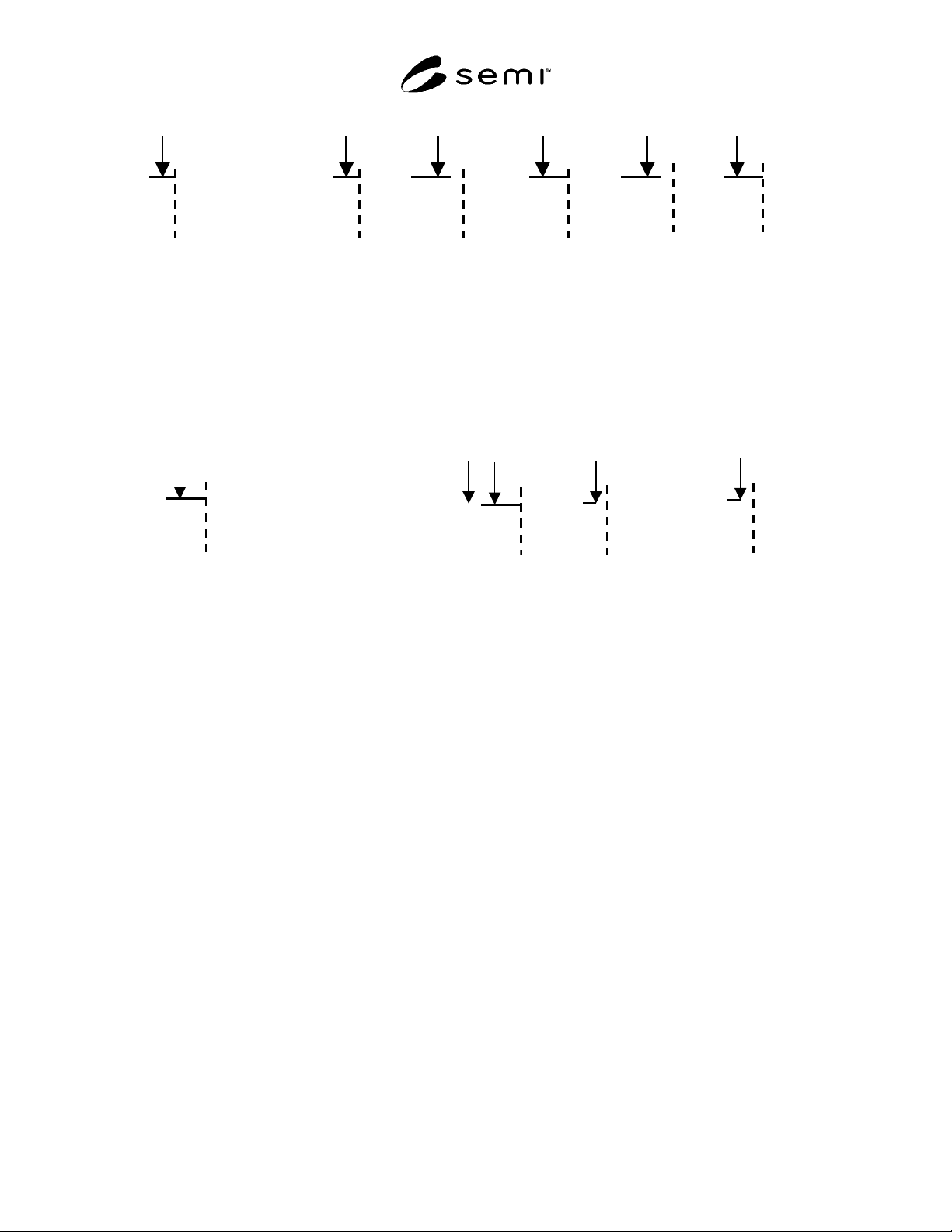
NOTE 1: In this figure, vertical dashed lines separate subfields; the concatenation and field identifiers are to the left of these
dashed lines. The CUSTOMER PRODUCT ID is a required field whose content is specified by the customer. The PART #
REVISION, SPECIFICATION #, SPECIFICATION # REVISION, DRAWING NUMBER and DRAWING NUMBER
REVISION are optional fields; these are also assigned by the customer up to a maximum character count of 35, including all
concatenation and field identifier characters. All unused character locations are filled with a dash (-).
Figure 2a
Example of Customer Information Field
DATA IDENTIFIER
CONCATENATOR
DATA IDENTIFIER
DATA IDENTIFIER
LOT NUMBER
SEMI
YYMMDD.
DATA IDENTIFIER
#
1T 1234567891234567+1V SV+D 960625+Q 25
NOTE 1: In this figure, vertical dashed lines separate subfields; the concatenation and field identifiers are to the left of these
dashed lines. LOT NUMBER is assigned by the supplier. SEMI represents the two-character vendor code that is maintained by
SEMI. YYMMDD represents the year, month and day of packaging and # is a two-digit number indicating the quantity of wafers
in the box.
Figure 2b
Example of Traceability Number