semi合集-English.pdf - 第1004页
SEMI E136-1104 © SEMI 2004 2 connect various parts of the RF power delive r y system. 5.2.2 calorimeter — an RF power measurement instrument using differential tem perature and mass flow rate to determine true heating po…

SEMI E136-1104 © SEMI 2004 1
SEMI E136-1104
TEST METHOD FOR DETERMINING THE OUTPUT POWER OF RF
GENERATORS USED IN SEMICONDUCTOR PROCESSING
EQUIPMENT RF POWER DELIVERY SYSTEMS
This test method was technically approved by the Global Metrics Committee and is the direct responsibility
of the North American Metrics Committee. Current edition approved by the North American Regional
Standards Committee on July 11, 2004. Initially available at www.semi.org September 2004; to be published
November 2004.
1 Purpose
1.1 The purpose of this test method is to provide an
accurate method for measuring the output power of RF
generators used in RF power delivery systems for
semiconductor processing equipment to support SEMI
E113.
2 Scope
2.1 This test method specifies the testing procedures
and test equipment required for determining the true
output power (i.e., heating power) output of RF
generators. This test method uses a calorimetric power
meter, which was calibrated previously using precise
DC substitution techniques as a reference standard.
2.2 The primary focus for this test method is
semiconductor processing equipment including, but not
limited to, the following equipment types:
Dry etch equipment, and
Film deposition equipment (CVD and PVD).
NOTICE: This standard does not purport to address
safety issues, if any, associated with its use. It is the
responsibility of the users of this standard to establish
appropriate safety and health practices and determine
the applicability of regulatory or other limitations prior
to use.
3 Limitations
3.1 This test method is meant to provide a general
means of measuring the true output power of RF
generators operating over a wide range of frequency
and power. Limitations in the frequency and power
coverage of this method are determined by the
individual system components chosen.
3.2 This test method assumes that the transmission
system characteristic impedance is 50 .
3.3 International, national, and local codes, regulations
and laws should be consulted to ensure that the
equipment and procedures meet regulatory
requirements in each location.
3.4 Certain safety issues associated with the test
procedures themselves are mentioned as a reminder that
safety procedures are necessary for safe conduct of the
test.
3.5 This standard does not address any safety or
performance issues related to RF emissions or electrical
codes (e.g., Underwriter’s Laboratory, Inc. (UL), the
National Electrical Code (NEC
), Federal
Communications Commission (FCC)). It is the
responsibility of the users of this standard to conform to
the appropriate local codes and regulations as applied to
this type of equipment, some of which are covered by
referenced documents.
4 Referenced Standards
4.1 SEMI Standards
SEMI E113 — Specification for Semiconductor
Processing Equipment RF Power Delivery Systems
SEMI E114 — Test Method for RF Cable Assemblies
Used in Semiconductor Processing Equipment RF
Power Delivery Systems
NOTICE: Unless otherwise indicated, all documents
cited shall be the latest published versions.
5 Terminology
5.1 Abbreviations and Acronyms
5.1.1 AC — Alternating Current
5.1.2 CVD — Chemical Vapor Deposition
5.1.3 DC — Direct Current
5.1.4 NIST — National Institute for Standards and
Technology
5.1.5 PVD — Physical Vapor Deposition
5.1.6 RF — Radio Frequency
5.1.7 VSWR — Voltage Standing Wave Ratio
5.2 Definitions
5.2.1 cable assembly — the section of cable
(transmission line), including the connectors, used to

SEMI E136-1104 © SEMI 2004 2
connect various parts of the RF power delivery system.
5.2.2 calorimeter — an RF power measurement
instrument using differential temperature and mass flow
rate to determine true heating power.
5.2.3 harmonic frequency — the harmonic frequencies
are defined as integer multiples of the fundamental
frequency. For example, the second harmonic of 13.56
MHz is 27.12 MHz.
5.2.4 RF generator — a component in the RF power
delivery system used to develop RF energy.
5.2.5 RF termination — a device for terminating RF
transmission systems, and converting RF electrical
energy into heat. RF terminations normally have values
that are the same as the characteristic impedance of the
transmission system.
5.2.6 RF load — another term used to describe an RF
termination.
6 Test Apparatus
6.1 Calorimetric Power Meter — This instrument is
designed to be used in conjunction with a high
efficiency water-cooled RF termination, rated for the
maximum power output of the RF generator. Typical
calorimetric power meters use internal thermocouple-
or thermistor-type temperature sensors, a precision
coolant flow meter, and processing circuits for storage
of calibration constants and coolant physical
characteristics. Choose instruments capable of
providing a power measurement accuracy of ± 1% after
calibration at a specific power level.
6.2 Water-Cooled RF Termination — This device
provides a low VSWR (i.e., high return loss)
termination for the testing of the RF generator. Use an
RF termination sized appropriately for the RF generator
under test. Finally, use an RF termination capable of
dissipating DC energy, without damage due to the
effects of electrolysis. The return loss of the RF
termination, including the interconnecting cable
between the RF generator and the termination shall be
no less than 30 dB. This return loss ensures maximum
power transfer between the RF generator and the
calorimeter.
NOTE 1: See Section 7 for safety-related recommendations
related to RF terminations.
6.3 Voltage and Current Meters — These meters are
used to measure the voltage and current presented to the
calorimeter load during the DC calibration of the
calorimeter. These instruments shall have a certificate
indicating NIST traceability. Choose meters capable of
voltage and current measurement accuracy of less than
0.2%.
6.4 Calibration Power Supply — This power supply is
used as a source of clean DC energy for the purposes of
calibrating the calorimetric power meter. Use a power
supply sized for the calibration to be performed and that
provides a very stable output at all levels.
6.5 Cables and Connectors — Various interconnecting
cables are required to perform the tests outlined in this
test method. These include low-loss cables to connect
the DC power source to the measuring instrument and
to the RF load, in addition to low-loss RF cables and
connectors to connect the RF generator output to the
load.
6.5.1 In order to keep cable losses to a minimum,
minimize the lengths of interconnecting cables.
6.5.2 In addition, compensate for the losses associated
with interconnecting cables used.
NOTE 2: For example, if 6 m (20 feet) of #10 AWG copper
wire is used to connect the DC supply to the calorimeter, this
wire will add approximately 0.04 of resistance between the
DC source and the 50 termination. Using a DC supply
voltage of 500 V terminated by 50 (i.e., 5 kW), this will
result in a loss of about 4 W in the copper wire.
6.5.3 Adjust the reading obtained by the calorimeter
according to the cable loss value.
NOTE 3: For example, suppose that an RF generator,
operating at 13.56 MHz and developing 3 kW is connected to
the calorimeter through a 6 m (20-foot) length of RG-217/U
coaxial cable. RG-217/U coaxial cable has a loss
specification of 0.41 dB per 30 m (100 feet) of cable at 13.56
MHz. Therefore, for 6 m (20 feet) of cable, the loss would be
approximately 0.41/5, or 0.082 dB. If the RF generator is
developing 3 kW, this means that approximately 2.944 kW
would appear at the calorimeter due to the cable loss.
7 Safety Precautions
NOTE 4: The tests described in this test method involve
using low-output power test instrumentation (typically less
than 10 mW).
7.1 Work should be conducted in accordance with
local safety requirements and test device
manufacturer’s recommended safety procedures.
7.2 The area immediately surrounding the test setup
should be kept free and clear of unnecessary equipment
and materials.
7.3 Testing personnel should ensure they have
SEMI E136-1104 © SEMI 2004 3
adequate lifting devices for large weights such as long
RF cables and generators themselves.
7.4 Persons performing tests should determine which
method of water cooling of the resistor in the RF
termination is utilized by the test device manufacturer
and should take steps to ensure safe use of the device.
7.4.1 Cooling-water flow rates should be appropriate to
the test device manufacturer’s recommendations for
cooling of the power load level being tested. Consult
the RF generator operating manual load specifications
for this information.
7.4.2 An RF termination using internal resistor cooling
only is highly recommended because such resistors (of
the tubular ceramic, thin film type) are usually cooled
by routing the coolant to the inside of the ceramic tube
and away from the resistive film, thereby eliminating
the possibility of electrolysis affecting the resistive
film.
7.4.3 In an alternative method, the coolant is routed on
both the inside and the outside of the resistor. While
this method provides for more efficient cooling, the
proximity of the coolant to the resistive film can
potentially result in damage to the resistive film caused
by electrolysis generated by the DC energy passing
through the fluid in the termination.
7.4.3.1 For this reason, if an RF termination using both
internal and external cooling is used, it is important to
periodically check the resistor for damage due to
electrolysis. This can be done easily by measuring the
resistance of the load resistor using a simple digital
multimeter.
7.4.3.2 With the RF termination disconnected from the
RF cable, place one probe on the center conductor of
the termination, and the other probe on the
termination’s outer conductor.
7.4.3.3 Measure the DC resistance of this path. If the
DC resistance is more than 53 , replace the resistor in
the termination.
7.5 In order to prevent the possibility of ground loops
between the RF generator and the calorimeter system,
be sure to operate the calorimeter and the RF generator
on the same AC supply.
8 Test Setup for RF Generator Power Output
Test
8.1 The test setup for the RF generator output power
test consists of the RF generator connected to the
calorimeter power meter through a length of coaxial
cable.
8.2 Prior to making any measurements, calibrate the
calorimeter power meter using a source of stable DC
energy.
9 Test Procedure for Determining RF
Generator Output Power
9.1 Calorimetric power meters provide excellent
reference standards for the measurement of RF energy
in that they are capable of measuring the true heating
power of a waveform, including any harmonic- or
nonharmonic-related frequency components. The
technique employed for this test is to first calibrate the
calorimetric power meter with DC energy, which can
be very precisely determined. Then, use two digital
multimeters (e.g., Fluke™ 87 or equivalent) to
determine the actual DC power applied to the
calorimeter. Finally, once the DC calibration has been
performed at a particular power level, connect the
output of the RF generator under test to the calorimeter
and measure the output power of the RF generator. The
basic steps involved in the use of this system are
outlined below.
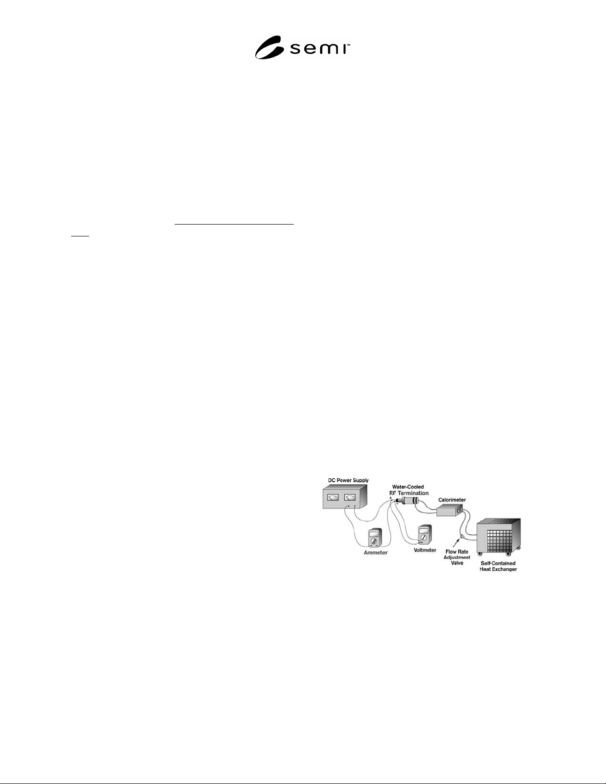
9.2 Calibrate the Calorimeter — Calibrate the
calorimeter with the stable DC power supply, using the
two digital multimeters to read the voltage and current
applied to the calorimeter’s RF load.
9.3 Connections — Connect the DC power supply, the
digital multimeters, and the RF load according to
Figures 1 and 2. Make the connections between the
multimeters, the DC power supply, and the RF load
using high-quality low-loss cable and high-quality
corrosion-free cable terminations.
Figure 1
Calorimeter Calibration Configuration