semi合集-English.pdf - 第772页
SEMI E104-0303 © SEMI 2000, 2003 8 9.2.2.8.2 The line system shoul d be smooth, conduc- tive, and electrically grounde d to minim ize electrostatic interaction of the particles with line walls a nd the parti- cles themse…

SEMI E104-0303 © SEMI 2000, 2003 7
wavelength of the incident light beam, diameter, shape, and
refractive index of the particle and the suspension fluid, as
well as on the geometrical layout of the collection optics and
detector. In the particle size range near the wavelength (0.1λ
< d
P
< 10λ), large oscillations can be seen in the intensity
curve of the light scattered by spherical particles as a function
of all these parameters. This phenomenon should be taken
into account when selecting a suitable set of particle sizes for
calibration. The used calibration particles should be within a
monotonic response range of the LPPD response curve.
9.2.1.2 Zero Gas
9.2.1.2.1 Clean air or nitrogen filtered with a ULPA
filter.
NOTE 5: The calibration will be executed under atmospheric
pressure and zero gas. In semiconductor manufacturing,
pressure and process gases will differ from the calibration
conditions. This will affect the refractive index ratio of the
particles and the process gas and consequently the scattering
from the particles.
9.2.1.3 Surfaces
9.2.1.3.1 The materials of pump lines and other
components should be conductive to minimize
electrostatic interaction with the particles.
9.2.2 Instrumentation (see Figure 1) — Some LPPDs
may require specialized equipment not generally
available. Please contact the LPPD manufacturer.
9.2.2.1 Fan System
9.2.2.1.1 The fan or pump system should be adjustable
to transport the aerosol and the zero gas within the
stipulated velocity range v
L, min
... v
L,max
, specified by
the manufacturer of the LPPD.
9.2.2.2 Filter System
9.2.2.2.1 The ULPA filter system is used for gener-
ation of zero gas. The filter system should be capable of
removing particles at the minimum size detectable by
the LPPD or the reference particle counter.
9.2.2.3 Aerosol Generator
9.2.2.3.1 An atomizer converts the monodisperse
particle suspension to an aerosol by using compressed
zero gas for generation and transportation of the
particles. The aerosol generator should generate
monodisperse particles as defined in Section 9.2.1.1 in
constant and reproducible concentration C
G
under
constant and reproducible volume flow rate V´
G
. The
variation in particle concentration shall be no more than
10% as measured by the reference particle counter over
a time period of 10 times or more of the sample
measurement time. The generation should comply with
the German VDI-Richtlinie 3491, or an equivalent
standard in other countries.
9.2.2.4 Aerosol dryer
9.2.2.4.1 The monodisperse polymer spheres in the test
aerosol shall be thoroughly dry to avoid that the
particles have a water layer which would increase their
size. A diffusion dryer, another appropriate instrument,
or adequately dry dilution air should be used to dry the
particles. The diffusion dryer uses silica gel desiccant to
remove the moisture. The desiccant shall either be new
or freshly regenerated. The design flow rate of the
aerosol dryer shall at least match the output flow rate of
the aerosol generator.
NOTE 6: Some diffusion dryers may precipitate polymer
spheres and add other particles when the aerosol gets in direct
contact with the silica gel.
9.2.2.5 Neutralizer
9.2.2.5.1 An aerosol neutralizer should be connected in
line with the dryer to reduce electrostatic charges on the
dry polymer spheres and to avoid electrostatic
interaction with each other or the line wall. The design
flow rate of the aerosol neutralizer shall at least match
the output flow rate of the aerosol generator.
NOTE 7: Some electrostatic neutralizers may produce a large
number of ultra-fine particles which will combine with the
calibration aerosol.
9.2.2.6 Aerosol Size Separator
9.2.2.6.1 In the case of calibration with ultra-fine
particles, a system should be used to separate single
polymer spheres from the residual particles resulting
from vaporization of solutions and aggregate particles
consisting of several spheres. The size separation could
be achieved with an electrostatic classifier or a
diffusion battery.
9.2.2.7 Aerosol Dilution
9.2.2.7.1 If the particle concentration behind the
aerosol generator is too high, the particle flow shall be
diluted to achieve the required concentration and to
avoid coincidence errors. The dilution should comply
with the German VDI-Richtlinie 3491, or an equivalent
standard in other countries.
9.2.2.8 Aerosol Line System
9.2.2.8.1 The system consisting of
• the aerosol generator,
• the aerosol dryer,
• the neutralizer,
• the particle size separator,
• the dilution stage, and
• tubing connecting the devices with each other and
the filtered, dried and compressed zero gas.

SEMI E104-0303 © SEMI 2000, 2003 8
9.2.2.8.2 The line system should be smooth, conduc-
tive, and electrically grounded to minimize electrostatic
interaction of the particles with line walls and the parti-
cles themselves. The line should be as short and straight
as possible with no bends with a radius of curvature less
than 100 mm. Leak-free connections of the line and all
devices should be ensured using appropriate fittings.
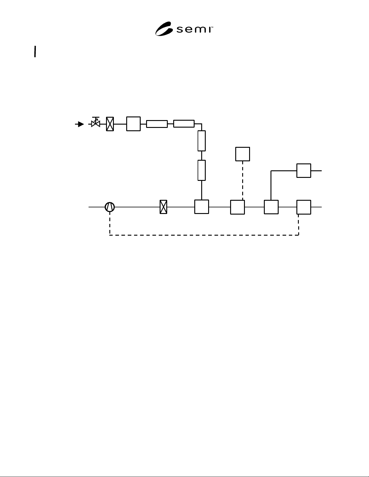
9.2.2.8.3 Figure 1 illustrates a recommended
calibration aerosol generation system.
9.2.2.9 Flow Control
9.2.2.9.1 The velocity of aerosol and the zero gas
should be within the stipulated range v
L, min
... v
L,max
,
specified by the manufacturer of the LPPD. Dependent
on the line diameter D
L
, a stipulated aerosol flow is
necessary. The velocity meter (e.g. thermoanemometer)
or flow meter should be mounted in a line with known
diameter D
VM
.
NOTE 8: The aerosol drawn by the reference particle counter
influences the velocity or flow measured by the velocity
meter or flow meter if it is mounted behind the probe inlet.
This is taken into account when calculating and adjusting the
flow and velocity v
L
at the LPPD. If the velocity meter or
flow meter is mounted in front of the probe inlet of the
reference particle counter, the device should have no
influence on the particle size distribution measured by the
reference particle counter.
9.2.2.10 Calibration Line System
9.2.2.10.1 The system consisting of
• a device to inject the particles into the zero gas,
• a device to mix the aerosol sample with the zero
gas to obtain uniform particle concentration,
• a device to adapt the LPPD into the line (diameter
D
L
),
• a device to adapt the velocity meter or the flow
meter,
• a device (diameter D
RC
= D
L
, same particle
concentration as at the LPPD) to draw a defined,
isokinetic sample from the line for the reference
particle counter (the opening area of the probe inlet
should be reported in the calibration report form),
and
• tubing connecting the devices with each other and
with the fan and filter system.
9.2.2.10.2 The line system should be smooth, conduc-
tive, and electrically grounded to minimize electrostatic
interaction of the particles with line walls and the parti-
cles themselves. The line should be as short and straight
as possible with no bends with a radius of curvature less
than 100 mm. Leak-free connections of the line and all
devices should be ensured using appropriate fittings.
9.2.2.10.3 Figure 1 illustrates a recommended LPPD
calibration system.
NOTE 9: The distance between the device to adapt the LPPD
under test and the device for sample acquisition for the
reference particle counter should be as short as possible to
minimize particle loss and to ensure comparable particle
concentrations.
9.2.2.11 Reference Particle Counter (RPC)
9.2.2.11.1 The reference particle counter is required to
measure the actual concentration of the monodisperse
aerosol and the quality of the zero gas inside the line.
Therefore, the counting efficiency of the reference
particle counter is defined as 100% over the range of
particle sizes used in the test. The resolution should be
better than 10% at the lower detection limit of the
LPPD under test. The values of the measurement
should be printed out in counts per mm
2
opening area
A
RC
of the probe inlet. The sample transit line from the
probe inlet and the reference particle counter should be
as short and as straight as possible. Smooth, conductive,
and electrically grounded materials should be used.
9.2.2.12 Sensor Window Temperature
9.2.2.12.1 Some LPPDs have the capability to heat
their sensor windows to avoid coating of the window. A
device to measure and to adjust the sensor window
temperature within the operating range (measurable to
5%) should be installed in the calibration setup. The
thermometer should be calibrated with an accuracy of
0.2° C.
9.2.2.13 Pulse Height Analyzer (PHA)
9.2.2.13.1 The external analyzer is connected with the
analog sensor calibration output. The PHA should have
at least 64 channels and a resolution of at least 1% of
the average voltage that will be measured. The use of a
PHA, which is built into the sensor electronics, is
allowed if this PHA meets the criteria mentioned above.
The required range and speed will depend on the
performance of the LPPD under test. These parameters
should be obtained by the LPPD manufacturer.
9.2.2.14 Environmental Monitoring
9.2.2.14.1 The environmental temperature T
A
is
measured by a thermometer calibrated with an accuracy
of 0.2° C.
9.2.2.14.2 The environmental relative humidity RH is
measured by a hygrometer.
9.2.2.14.3 The atmospheric pressure p is measured by a
barometer calibrated with an accuracy of 133 Pa.
SEMI E104-0303 © SEMI 2000, 2003 9
9.2.2.15 All instruments used for the reference calibration procedure shall have been checked for valid calibration
in accordance with ISO 10012-1 and 10012-2. Record all calibration data.
9.2.3 Setup and Schematic
9.2.3.1 See Figure 1.
Neutralizer
Dryer
Aerosol
Generator
ULPA
Filter
Compressed,
Dried Air
Dilution
Aerosol Size
Separator
PHA
Fan
ULPA
Filter
LPPD
Analog Output
Reference
Particle
Counter
Injection and
Mixing Device
V´
L
, C
L
,
D
L
, v
L
D
VM
, v
VM
V´
G
C
G
V´
0
Velocity or Flow
Meter and Control
D
RC
Sample
Acquisition
Device
Figure 1
Calibration setup and schematic
9.3 Calibration Procedure
NOTE 10: Specific procedures for calibrating different
LPPDs can vary considerably not only between manufacturers
but between instrument models. For this reason, this
document cannot provide detailed procedures for calibrating
every LPPD. For detailed procedures for calibrating a specific
LPPD, contact the manufacturer. The calibration should be
performed by a skilled technician.
9.3.1 If the aerosol flow rate is varied, then particle
residence time in the detection area A
L
will also vary.
This results in pulses of varying duration. Therefore,
the particle velocity v
L
at the LPPD should be constant
and independent of the line diameter D
L
. The fan has to
be regulated so that the aerosol velocity at the velocity
meter is v
VM
= v
L
D
2
L
/ D
2
VM
. At a constant volume
flow rate V´
G
(depending on the pressure of the
compressed air) and constant number concentration C
G
the level of number concentration C
L
reaches a value
dependent on line diameter D
L
at constant velocity v
L
.
With the known detection area A
L
of the LPPD, the
number of particles per time (counts per mm
2
detection
area per time) is defined. The RPC monitors the number
of particles C
L
of the aerosol generator and the zero air
inside the line.
9.3.2 If the response signal for the used particle size
does not meet the expectations, the operator might use
another particle size within the required size range.
9.3.3 Calibration Parameters
9.3.3.1 The sample measurement time for the
calibration with each particle size should be at least 30
seconds to avoid statistical errors.
9.3.3.2 The calibration is to be performed at ambient
atmospheric pressure in a controlled environment
(temperature, humidity, vibrations).
9.3.3.3 The calibration of the LPPD is to be executed
in a line diameter D
L
in which the LPPD should be
installed by the user.
9.3.3.4 Fixed particle concentration at the LPPD C
P
to
ensure that the coincidence error is always less than
10%.