semi合集-English.pdf - 第2747页
SEMI E98-1102 © SEMI 2000, 2002 12 Table 1 Funct ional Area Definition Functional Area Where Defined Comments Access Management SEMI E98 (OBEM) Defi nes different kinds of user co ntrol. Date/Time Managem ent SEMI E 98 (…

SEMI E98-1102 © SEMI 2000, 2002 11
internal subsystems, subassemblies, and i/o devices
used in moving material within the equipment, such as
robots, location sensors, proximity sensors, motors,
centering and alignment systems, and material identifier
readers.
8.3.15 Object Management
8.3.15.1 Object Management consists of management
of OBEM objects, their attributes, and internal
communications. It includes all elements of
configuration definition, both fixed and user-
configurable, that pertain to the equipment.
Configuration settings consist of those attributes that
affect the global behavior of the equipment and are
generally static and change only on request. They are
in effect at all times regardless of the current recipe(s)
and/or processing states. They control activities that
maintain the environment when “not processing”.
8.3.15.2 Configuration settings shall be retained in
non-volatile storage. Some elements of configuration
may be distributed. For example, individual process
chambers may have their own configuration elements.
8.3.15.3 Elements of configuration management
include:
• configuration of individual physical chambers, and
• configuration of individual logical objects.
8.3.16 Operations Management — Operations
Management is responsible for the overall operation of
the equipment in all operational modes: automatic,
semi-automatic, and manual.
8.3.17 Performance Management — Performance
Management is responsible for managing information
and operations related to the performance of the
equipment and equipment modules. This includes
oversight for manual mode operations performed when
the equipment and equipment modules are out of
service. For implementations of ARAMS, this also
includes ARAMS state changes and data as well as
oversight for manual mode operations performed during
downtime and non-scheduled time.
8.3.18 Process Execution — Process Execution covers
those fixed algorithms and procedures that are not
reachable or changeable by the user. This includes any
embedded control and sequence algorithms not
contained in recipes. It consists of low-level control of
subsystems, sensors, and actuators not covered by
Material Management Control, such as, chemical
control (valves, exhaust), motion control (rotational,
acceleration, positional) and the control of the
environment during processing of the product
(temperature, etc.). It also includes product
environment control and any fixed embedded fault
detection classification, and/or fixed low-level in-situ
run-to-run control for advanced process control.
8.3.19 Recipe Execution
8.3.19.1 A recipe represents the pre-planned and
reusable set of instructions, algorithms, and settings that
are used by process execution to control process,
including variable in situ process control algorithms.
Recipes are created by the user, and in some cases by
the equipment as well. Recipes may be of a variety of
types, such as flow sequence, metrology, models, abort,
and load maps, as well as etch, clean, etc.
8.3.19.2 Recipe Execution is responsible for the proper
and safe execution of recipes, including loading the
recipe into the execution area, verification of the recipe,
validation of recipes (ensuring the recipe does not
conflict with the current equipment configuration), and
initiation of process execution based on recipe
instructions (SEMI E42).
8.3.20 Recipe Management — Recipe Management
consists of the management of stored recipes. This is
differentiated from short-term storage of recipes and the
selection and execution of recipes performed by Recipe
Execution (SEMI E42). Recipes are classified
(organized) according to their primary application
function: process, environment, service (maintenance),
etc.
8.4 Relationships with Other Standards
8.4.1 Only those functional areas in the middle in
Figure 1 are of interest to the host. The top level of
Equipment Control represents all of the functionality
below it, while the functional areas at the bottom are
considered to be low level and proprietary to the
equipment supplier.
8.4.2 Table 1 shows those functional areas that are
defined by OBEM and those that are defined by other
SEMI standards. In some cases, OBEM may extend or
limit the functionality defined elsewhere.
SEMI E98-1102 © SEMI 2000, 2002 12
Table 1 Functional Area Definition
Functional Area Where Defined Comments
Access Management SEMI E98 (OBEM) Defines different kinds of user control.
Date/Time Management SEMI E98 (OBEM) Addresses timestamp, date/time synchronization.
Event Management SEMI E53 (ERS) SEMI E53 may be required for SECS-II implementations.
Exception Management SEMI E41 (EMS) Required for reporting alarms and exceptions.
Material I/O Management SEMI E87 (CMS) Required for Carrier Management.
Material Management SEMI E90 (STS) Required for Substrate Tracking.
Object Management SEMI E39 (OSS) Required
Operations Management SEMI E98 (OBEM) Overall coordination.
Performance Management SEMI E58 (ARAMS) Optional for EquipmentModule and Equipment. Not used
for lower level components.
Job Management SEMI E40 (PM),
SEMI E94 (CJM)
Process Managment and Control Job Management
Recipe Execution SEMI E42 (RMS) Required for processing by EquipmentModule.
Recipe Management SEMI E42 (RMS) Required for long-term storage by Equipment.
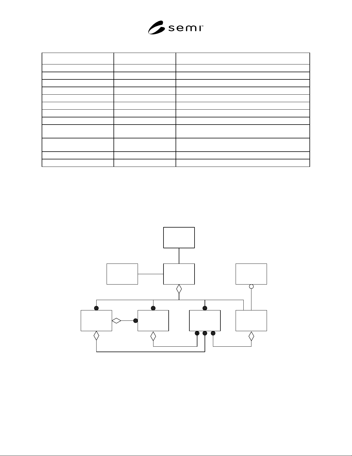
8.5 Internal Composition View of the Equipment — The physical makeup of equipment is of interest to the factory,
particularly for equipment that is complex, multi-module, and/or multi-process. Productivity and maintenance
tracking, for example, requires that the factory be able to specify individual subsystems and/or modules for
maintenance activities, where it is possible to do so without removing the entire equipment from manufacturing
scheduling. For example, one or more baths in a wet bench may be down for maintenance even though the wet
bench itself continues to process.
1+
1+
held at
interacts with
EquipmentClock
Process
Module
Material
Handling
Subsystem
I/O Device
User
Carrier
LoadPort
1+
Figure 2
An Example of Equipment Internal Composition
9 OBEM Object Model
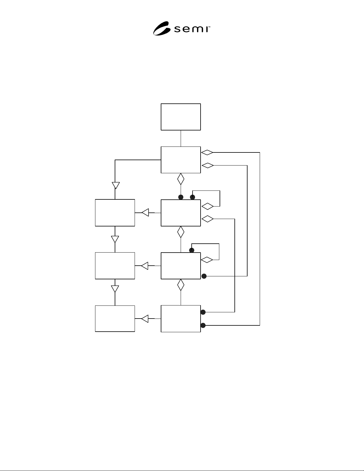
9.1 OBEM defines generic component objects of Equipment, and the Equipment object itself. Equipment is made
up of elements (units or parts) of different levels of intelligence and complexity, such as modules, subsystems, and
I/O devices. Each of these elements may itself be made up of several smaller elements, some of which may also be
intelligent, and this allows the complexity of the equipment to be distributed to smaller functional units. Many of
SEMI E98-1102 © SEMI 2000, 2002 13
these elements may be of interest to the factory. In particular, process modules, which are intelligent and may be
independently operable, are very interesting to the factory, since these are the units where the product is actually
processed. The factory requires processing modules to be highly visible and individually addressable and to support
certain of the same remote commands that are required of the equipment. Other elements of interest include
subsystems for material handling, alignment, and measurement.
9.2 The equipment is responsible for all communications at all times, including messages directed to a specific part
of the equipment. Service requests directed to components of the equipment shall be managed by the equipment to
ensure equipment integrity.
Equipment
Module
Equipment
Equipment
Subsystem
Abstract
Equipment
Element
Equipment
IODevice
Abstract
Equipment
Subsystem
Abstract
Equipment
Module
User
1+
Figure 3
Equipment Object Model
9.3 In Figure 3, two hierarchies are shown. On the left is an inverted interface inheritance hierarchy, and on the
right the concrete subtypes where rules of aggretation are shown. The interface inheritance shows the objects that
define the attributes, state models, and services of the subtype objects as viewed externally. These are presented
upside down from the usual presentation so that they may be directly related to the aggregation hierarchy on the
right. In both cases, the simpler objects are below the more complex objects.
9.4 Those object types starting with the word “Abstract” are abstract objects not intended to be implemented
directly. Their purpose is solely to define the inherited attributes, state models, and services for those objects used
to build an OBEM model of equipment. The remaining objects shown in Figure 3 are concrete objects. All rules of
aggregation are defined for concrete objects only.