semi合集-English.pdf - 第6597页
SEMI C1-0705 © SEMI 1978, 2005 23 7.13.4 Evaporatio n of Sample s — Liquid chem ical matrix elements m ay be the source of spectral interfe rences on certain target elements e.g. 48SO interferes with 48Ti in a sulfur ic …

SEMI C1-0705 © SEMI 1978, 2005 22
7.13 Determination of Trace Elements by Inductively Coupled Plasma Mass Spectrometry (ICP-MS) — The
determination of trace elements in liquid chemicals which are commonly used in advanced semi-conductor
manufacturing requires a sensitive technique with the ability to perform simultaneous analysis for multiple elements.
Achievable detection limits are adequate for sample analysis with little sample preparation prior to analysis. Liquid
chemical matrix reduction needed to perform routine analysis is often achieved by dilution of the sample. Water
used for dilution should be the appropriate grade of 18.2 Mohm-cm water that meets ASTM Standard Guide D5127.
Matrix removal methods which require sample evaporation should be performed under HEPA filtered air such that
reproducible blank samples are obtained at or less than one half the specified limit of trace elements for the sample.
No specific procedure for inductively coupled plasma mass spectrometry is included since instrumentation and
practices vary among laboratories. Some practical considerations relevant to the method are outlined below.
7.13.1 Equipment — A mass spectrometer with better than 1 amu resolution from 5–250 amu is required to separate
the isotopes of the elements stated in the specification for an individual liquid chemical. The use of hot or cool
plasmas as well as a collision/reaction cell may be required to meet the SEMI detection limit requirements for
certain analytes. The signal from the detector is digitized by a computer system for quantitative calculation.
Interference correction may be required for some isotopes. Typical analytically useful masses are listed in Table 11.
Table 11 Suggested Analytical Masses
Element Masses
Aluminum (Al) 27
Antimony (Sb) 121, 123
Arsenic (As) 75
Barium (Ba) 137, 138
Boron (B) 11
Cadmium (Cd) 111, 114
Calcium (Ca) 40
Chromium (Cr) 52
Copper (Cu) 63, 65
Iron (Fe) 56
Lead (Pb) 206, 207, 208
Lithium (Li) 7
Magnesium (Mg) 24
Manganese (Mn) 55
Nickel (Ni) 58, 60
Potassium (K) 39
Sodium (Na) 23
Tin (Sn) 118, 120
Titanium (Ti) 48
Vanadium (V) 51
Zinc (Zn) 64, 66
7.13.2 Sample Introduction — Conventional glassware used for sample introduction is in most cases appropriate for
liquid chemical analysis, however for Grade 5 liquid chemicals an ultra clean sample introduction system is
recommended. Liquid chemicals containing hydrofluoric acid (HF) require a HF resistant introduction system
unless the hydrofluoric acid matrix is removed prior to the analysis.
7.13.3 Ionization Source — An inductively coupled plasma using argon as the support gas has proven to be
satisfactory as an ionization source for the method. Ionization conditions present in the argon plasma are highly
dependent on the various argon gas flow rates used to support the plasma. Sample introduction techniques used to
introduce the sample into the plasma are important to the analysis of the samples and must be optimized to allow
successful analysis. In particular, sample uptake and nebulizer gas flow require special attention and should be
treated carefully in order to optimize instrument performance for each of the various liquid chemicals.
SEMI C1-0705 © SEMI 1978, 2005 23
7.13.4 Evaporation of Samples — Liquid chemical matrix elements may be the source of spectral interferences on
certain target elements e.g. 48SO interferes with 48Ti in a sulfuric acid matrix when using quadrupole-based ICP-
MS. Such spectral interferences may be significantly reduced or eliminated by controlled evaporation of the sample
followed by dissolution and analysis in ultrapure nitric acid or other suitable solvent.
7.13.5 Solution Conditions — The solutions are prepared as given in the procedures for the individual liquid
chemicals or elements.
7.13.6 Working Standard Solutions — Working standard solutions are prepared daily by dilution of stock standard
solutions. Internal standard solutions, if used, are prepared similarly.
7.13.7 Quantification — Quantification may be performed by the method of standard additions or by external
calibration. External standards may also be matrix matched in ultra pure liquid chemicals to assure that plasma
conditions during the analysis are similar for both standards and samples. For those liquid chemicals, which require
matrix removal, the preferred matrix after preparation is dilute nitric acid (typically 1–3%.) The working standard
solutions are prepared to cover the expected range of trace element concentration. Background subtraction by use of
a reagent blank solution is may be used for sample analysis by this technique.
7.13.8 One or more internal standards (such as indium or rhodium) may be used for drift correction during the
analysis.
7.13.9 Remarks — The manufacturer’s manual should be consulted for details specific to the operation of the
instrument. Performance checks on the instrument should be made from time to time to assure adequate mass
resolution, performance, and sensitivity.
7.14 Calibration and Measurement Method for Particles in Liquids — This standard describes the apparatus and
methods used to calibrate optical particle counters (OPCs) and to count hard particles in liquid reagents. The
procedures in this standard provide a means of comparison of particle levels in various reagents using pressurized
sampling and counted using the various available instruments. While the procedures in this standard are primarily
directed at off-line sampling or sampling from containers, OPCs can also be used for continuous on-line particle
measurement. While some substantial technical difficulty may accompany the implementation of the pressurized
sampling technique for containers of more than 10 L, the method should be followed as closely as possible to
maximize the integrity of the data. The following procedures are partially based on the publications in the attached
bibliography, which should be consulted for further details.
7.14.1 Apparatus — The apparatus used to measure the concentration of particles in reagents is comprised of a
sample supply system, a particle counter, and a flow measurement and control system. Two manual flow
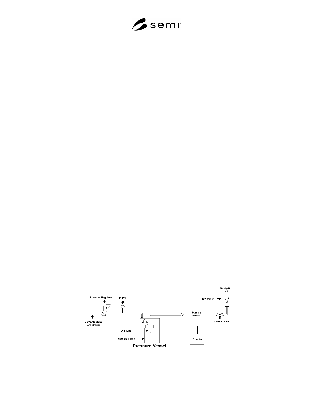
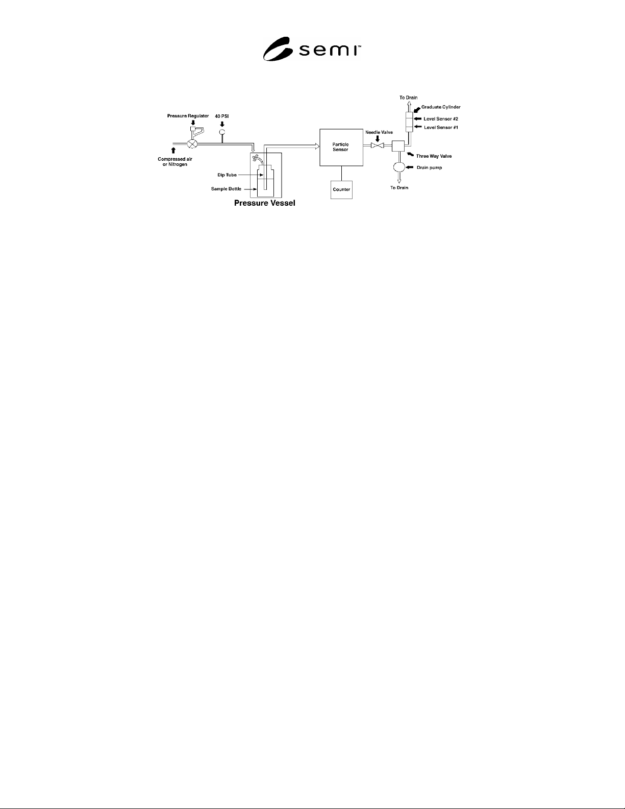
measurement and control systems are presented in Figures 4 and 5. Several manufacturers have developed
automated pressurized sampling systems.
7.14.2 Discrete Sample Supply System — In the method specified in this standard, the pressure in the reagent
container is raised sufficiently above atmospheric pressure to produce the required flow and to reduce microbubble
formation, which causes falsely high counts. Pressurizing containers of reagents presents a substantial safety
hazard. Several systems have been developed for pressurizing the contents of a reagent container without placing a
pressure differential across the reagent container wall. A pressurized sampling system is required for all reagents.
Figure 5
Pressurized Test System
SEMI C1-0705 © SEMI 1978, 2005 24
Figure 6
Pressurized Test System
7.14.2.1 The reagent container is placed in a canister suitable for use as a pressure vessel at 4 bar (60 psi), such as a
large steel filter housing. The interior of the canister should be resistant to corrosion by the reagents being tested.
This canister is fitted with a relief valve set at 3.5 bar (50 psi), a nitrogen inlet, and a sealed feed-through for the
sample tube. The reagent container is fitted with a perfluoroalkoxy (PFA) cap to which is attached a hydrophobic
polytetrafluoroethylene (PTFE) nitrogen inlet filter. This permits the nitrogen pressures inside and outside the
reagent container to equilibrate when the vessel is pressurized and prevents particles from the pressure canister from
entering the sample reagent container.
7.14.2.2 Either of two sample and dip tube configurations may be used. In the first, a PFA dip tube, which extends
to 5 cm from the bottom of the reagent container, is attached to the cap. The sample tube, which consists of a single
continuous piece of PFA tubing to reduce the chance of incidental contamination during measurement, is connected
to the cap and the particle counter. This configuration has the advantage that it allows the sample tube to be
disconnected from the cap and dip tube, reducing the risk of splashing and of cross-contaminating samples. The
disadvantage of placing a fitting between the sample and the counter is that the fitting may compromise the integrity
of the sample.
7.14.2.3 In the second configuration, a single tube, without valves, fittings, or discontinuities extends from the
counter, through the cap to 5 cm from the bottom of the reagent container. This has the advantage that it ensures the
integrity of the sample but the disadvantage is that the risk of splashing and cross-contamination is increased.
7.14.3 Particle Counter — Laser light scattering OPCs from any of several suppliers may be used provided they are
in calibration, and used subject to the limitations described in ¶7.14.3.1.
7.14.3.1 Limitations on Counting Particles in Liquid Reagents using OPCs — OPCs are calibrated using
polystyrene latex (PSL) beads suspended in high purity water. The optical properties of naturally occurring particles
in liquid reagents are different from the optical properties of PSL and water. OPCs detect “light-scattering centers”
and calculate particle size and concentration based on the assumption that the light-scattering centers are equivalent
to PSL in water. In reality, light scattered by a particle is dependent upon particle size, particle shape and the
difference between the particle’s refractive index and the refractive index of the surrounding medium. When
properly calibrated OPCs from different manufacturers are used to measure particles in high purity water, they give
comparable size and concentration data.
7.14.3.1.1 Commercially, OPCs are manufactured with different illuminating wavelengths and a variety of optical
arrangements for collecting light scattered by particles. Because of the significant difference in the refractive index
of particles relative to the refractive index of water, the resulting scattered light profile is readily detected by all
OPCs. Hence there is relatively good comparative agreement between OPCs when used to detect particles in high
purity water.
7.14.3.1.2 When calibrated OPCs are used to measure particles in semiconductor liquid reagents, a totally different
situation is encountered. The refractive index of liquid reagents varies significantly from water and is, in general,
greater than water. While the refractive index of reagents is known and can be adjusted for, the refractive index of
particles is unknown and, in many circumstances, is expected to be very close to the refractive index of reagents.