semi合集-English.pdf - 第6432页
SEMI G75.9-069 8 © SEMI 1998 2 8 Related Documents NOTE: As liste d or revised, a ll documents cite d shall be the latest public ations of adopted standards. 8.1 AST M Specification 1 ASTM D 638 — S tandard Test Method f…

SEMI G75.9-0698 © SEMI 19981
SEMI G75.9-0698
TEST METHOD FOR MEASUREMENT OF TENSILE STRENGTH,
ELONGATION, AND TENSILE MODULUS OF LEADFRAME TAPE
1 Purpose
1.1 Tensile strength, elongation, and tensile modulus
of leadframe tape are measured by a tensile pull tester,
which is used to stretch the tape samples to the point of
breakage with a calibrated load cell.
2 Equipment
2.1 Tensile pull tester with 100 kg MAX load cell,
sample clamping chucks, and a chart recorder.
2.2 Micrometer with 0.001 mm accuracy.
2.3 Calipers with 0.02 mm accurac y.
3 Test Condition
3.1 Tensile test measurements shall be carried out at
the following ambient conditions:
Temperature — 23 ± 5°C
Humidity — 50 ± 5% RH
4 Sampling
4.1 The sampling is one sample per one lot. The
vendor has to report the definition of lot, if the
customer requires it.
4.2 The sample width shall be 15.0 ± 0.2 mm, and the
length must be 100 mm minimum.
5 Equipment Setup and Cal ibration
5.1 Refer to the tensile tester manufacturer’s
equipment manual for setup and calibration.
5.2 The pulling rate shall be set to 5 ± 0.5 mm/minute.
5.3 The load shall be recorded in kilograms.
6 Procedure
6.1 Measure the thickness (T) of the sample with the
micrometer and the width (W) with calipers (mm).
6.2 Clamp the tape in the chucks so that the distance
(L
0
) between the chucks is 50 ± 5 mm.
NOTE: Some equipment may measure this length
automatically or plot Stress versus Strain, (L/L
0
), directly,
where L is the elongation.
6.3 Start the pulling and record until the sample
breaks.
6.4 Repeat the testing procedures for all the samples.
7 Results
7.1 Read the Break Force A (kg) and Elongation L
1
(mm) at sample breakage from the chart.
7.2 Draw a tangent line from the origin of the Load-
Elongation curve to the maximum slope of the curve.
(See Figure 1.)
NOTE: B (kg) is the incremental force change required to
produce an elongation, L
2
, in the elastic region and may be
determined from the tangent line.
Figure 1
Breakage Point Calculation Diagram
7.3 Calculations — Tensile Strength at Break (s) is
determined from the following equation:
S(
N
/
mm
2
)
=
9
.
8
A
WT
7.3.1 Percentage Elongation at Break (e) is determined
from the following equation:
ε
(%)
=
100
L
1
L
0
7.3.2 Tensile Modulus (E) is determined from the
following equation:
E
(
N
/
mm
2
)
=
∆
Stress
∆
Strain
=
9
.
8
B
WT
L
2
L
0

SEMI G75.9-0698 © SEMI 1998 2
8 Related Documents
NOTE: As listed or revised, all documents cited shall be the
latest publications of adopted standards.
8.1 ASTM Specification
1
ASTM D 638 — Standard Test Method for Tensile
Properties of Plastics
8.2 JIS Specification
2
JIS K 6911 — Testing Methods for Thermosetting of
Plastics
NOTICE: These standards do not purport to address
safety issues, if any, associated with their use. It is the
responsibility of the user of these standards to establish
appropriate safety and health practices and determine
the applicability of regulatory limitations prior to use.
SEMI makes no warranties or representations as to the
suitability of the standards set forth herein for any
particular application. The determination of the
suitability of the standard is solely the responsibility of
the user. Users are cautioned to refer to manufacturer’s
instructions, product labels, product data sheets, and
other relevant literature respecting any materials
mentioned herein. These standards are subject to
change without notice.
The user’s attention is called to the possibility that
compliance with this standard may require use of
copyrighted material or of an invention covered by
patent rights. By publication of this standard, SEMI
takes no position respecting the validity of any patent
rights or copyrights asserted in connection with any
item mentioned in this standard. Users of this standard
are expressly advised that determination of any such
patent rights or copyrights, and the risk of infringement
of such rights, are entirely their own responsibility.
1 American Society of Testing and Materials, 100 Barr Harbor Drive,
West Conshohoken, PA 19428-2959 (all cited standards may be
found in Volume 10.05 of the Annual Book of ASTM Standards)
2 Japanese Standards Association, 1-24, Akasaka 4 Chome, Minato-
ku, Tokyo, Japan
Copyright by SEMI® (Semiconductor Equipment and Materials
International), 3081 Zanker Road, San Jose, CA 95134. Reproduction o
f
the contents in whole or in part is forbidden without express written
consent of SEMI.
SEMI G75.10-0698 © SEMI 19981
SEMI G75.10-0698
TEST METHOD FOR MEASUREMENT OF VOLUME AND SURFACE
RESISTIVITY OF THE LEADFRAME TAPE
1 Summary of Method
1.1 A resistance is measured across the thickness and
along the surface of the adhesive of tape between
electrodes deposited on the tape. Volume and surface
resistivity are calculated from these resistances and the
dimensions electrodes.
2 Equipment
2.1 Power Source — 500 volts DC battery or 500
volts rectified voltage supply.
2.2 Amplified galvanometer should be used for
measuring insulating resistance no less than 10
6
Ω.
2.3 Electrostatically and electromagnetically shielded
box
2.4 Humidity-controlled storage box
2.5 Micrometer — 0.001 mm accuracy
3 Sampling
3.1 The sampling is one sample per one lot. The
vendor must report the definition of lot, if the customer
requires it.
4 Preparation of Specimens
4.1 The specimen shall be punched out from tape, the
diameter of which has to be no less than that of the
opposite electrode.
4.2 Place the specimens in the con stant humidity box
23° ± 2°C and 50 ± 5% RH for 90 ± 2 hours. This may
also be done after the electrodes are formed.
5 Test Conditions
5.1 Temperature — 23° ± 2°C
5.2 Relative Humidity — 50 ± 5% RH
5.3 Applied Voltage — 500 volts
6 Procedure
6.1 Measure the thickness of specimen with the
micrometer. Attach the electrodes to the specimen.
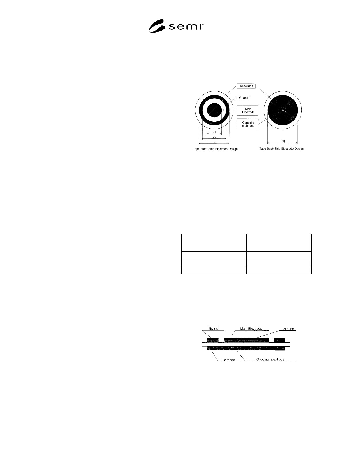
Electrodes are formed by conductive epoxy printing or
aluminum evaporation shown in Figure 1.
Figure 1
Electrodes Formed on the Leadframe Tape
NOTE 1: The electrodes shall be formed on both sides of the
tape.
NOTE 2: Suggested dimensions for the electrodes as shown
in Table 1 (d
1
–d
2
) should be at least 10 times the tape
thickness.
Table 1 Suggested Dimension of the Electrodes
Suggested Dimension(for tape
thickness 0.063–0.077 mm)
Value
d1 18 mm
d2 20 mm
d3 30 mm
NOTE 3: At surface resistivity measurement, main electrode
and guard electrode is attached to the adhesive surface.
6.2 Place the specimens in the electrode system as
shown in Figure 2A.
Figure 2A
Volume Resistivity Electrode Connection