semi合集-English.pdf - 第323页
SEMI E49.2-1104 © SEMI 1995, 2004 5 such that the te sts are representative of the Assembly performance. 9.1.6 For optimum resu lts, the distance between a sample port an d an instrum ent should be minimized. It is recom…

SEMI E49.2-1104 © SEMI 1995, 2004 4
7 Utility Recommendations
NOTE 3: These are minimum utility recommendations for
the media used during qualification of an Assembly.
7.1 Nitrogen
Nitrogen quality should meet requirements of
SEMI C59.
Particle filtration should be 99.99999% removal of
.003 micron particles.
7.2 Ultrapure Water
Resistivity 18 Mohm-cm @ 25°C (77°F)
TOC — < 10 ppb
Silica — < 5 ppb
Particles — (>
0.1 µm) < 500 particles/L
Anions (F-, Cl-, NO2-, Br-, NO3-, HPO4-, SO4-) <
0.10 ppb
Metals (Al, Ba, B, Ca, Cr, Cu, Fe, K, Li, Mg, Mn,
Na, Ni, Pb, Sr, Zn) < 0.05 ppb
Bacteria — < 10 colonies/100 milliliter
NOTE 4: If testing requirements dictate, access to higher
quality Ultrapure Water may be appropriate. Additional
information related to Ultrapure Water facility design and
terminology may be obtained in SEMI F61, Guide for
Ultrapure Water System Used in Semiconductor Processing.
7.3 Clean Dry Air (CDA) or Oil Free Air — Uses
include pneumatic control and air actuation. CDA is
not recommended for use on cleaned wetted surfaces.
Nitrogen is recommended for drying cleaned wetted
surfaces because the purity level is clearly defined and
controlled.
8 Related Documents
8.1 International SEMATECH Documents
3
SEMASPEC 92010936B — Provisional Test Method
for Determining Leachable Trace Inorganics in Ultra
Pure Water Distribution System Components
SEMASPEC 92010937B — Provisional Test Method
for the Evaluation of Bulk Polymer Samples of Ultra
Pure Water Distribution System Components
SEMASPEC 92010949B — Provisional Test Method
for Determining Particle Contribution and Retention by
Ultra Pure Water Distribution System Components
3 International SEMATECH, 2706 Montopolis Drive, Austin, TX
78741, USA, Website: www.sematech.org
SEMASPEC 92010955B — Provisional Test Method
for Analyzing Plastic Surface Condition of Ultra Pure
Water Distribution System Components (SEM Method)
8.2 ASTM Documents
ASTM D5173-97 Standard Test Method for On-
Line Monitoring of Carbon Compounds in Water by
Chemical Oxidation, by UV Light Oxidation, by Both,
or by High Temperature Combustion Followed by
NDIR or by Electrolytic Conductivity
9 Sampling and Analysis Methodology
9.1 General Recommendations for all Tests
9.1.1 All test reports should include:
Confidence intervals and detection or reporting
limits,
All units of measure,
As detailed a description as possible of the
Assembly tested including part number and
manufacturing date,
Date of test and initials of person performing test,
Additional information as specified in the specific
test recommendations within this document,
Any and all relevant data collected during testing
should be summarized and included,
Recording of Ultrapure Water and Nitrogen quality
used to perform test, and
For Sections 9.3 through 9.5 inlet and outlet water
quality.
9.1.2 Trained and qualified personnel should perform
all sampling and testing.
9.1.3 All instrumentation shall be calibrated with
standards traceable to NIST or the equivalent national
standard where those standards exist. The type of
instrument(s) manufacturer, model #, serial # or I.D #,
and most recent calibration date should be available.
9.1.4 If using two separate online instruments for inlet
and outlet testing, determine any difference in the two
readings and include that in the final calculations.
9.1.5 Incoming and outgoing water should be sampled
as close as possible to the Assembly’s liquid supply
point and the Assembly’s delivery point respectively.
Where there are multiple inlets and/or outlets for an
Assembly, a single representative inlet and outlet
should be selected for this testing. However, all inlets
and outlets should be flushed in a consistent manner
SEMI E49.2-1104 © SEMI 1995, 2004 5
such that the tests are representative of the Assembly
performance.
9.1.6 For optimum results, the distance between a
sample port and an instrument should be minimized.
It
is recommended that components comply with SEMI
F57 and the assembly and design should be in
accordance with SEMI E49.7.
9.1.7 Operate valves to ensure there is no entrapment
and to displace any air prior to beginning a test.
9.1.8 Filter elements contained within the Assembly
under test should not be included during a test as they
may mask results and will need to be replaced
following the test.
9.1.9 Assemblies
should be dried with Nitrogen and
capped following any testing with ultrapure water and
prior to shipment.
9.2 Hydrostatic Pressure Test – This test is required
for every Assembly shipped directly to an end user.
This test may also be required periodically at other
points in the supply chain.
9.2.1 The intent of this test is to eliminate Assembly
leaks when an assembly is initially exposed to pressure
and temperature (up to and including the
manufacturer’s maximum recommended operating
pressure and temperature) at the end user’s facility.
The user of this test is encouraged to review
“Hydrostatic Pressure and Leak Testing of Polymer
Piping Systems Used in High-purity Water
Applications” (Mayer, Burkhart, Rydzewski) for a
thorough discussion of standards, and how the physical
properties of polymers impact testing practices.
9.2.2 The Hydrostatic Pressure Test conditions are the
manufacturer’s maximum recommended pressure at
ambient temperature. However, it is incumbent upon
the manufacturer to ensure that the assembly will be
leak free when exposed to maximum pressure and
maximum temperature at the end user’s facility. If the
test conditions recommended here do not result in
initial leak free operation for the end user, it is
incumbent upon the end user and manufacturer to agree
on appropriate corrective action(s) to comply with the
intent of this Hydrostatic Pressure Test. This may
include testing at elevated media temperatures.
9.2.3 Test Method
9.2.3.1 Test Media — Ultrapure Water at ambient
temperature.
9.2.3.2 Test Pressure — Manufacturer’s maximum
recommended operating pressure.
9.2.3.3 Test Procedure
Flush system at maximum rated flow to remove
entrapped air.
Keep assembly at constant temperature during test.
Pressurize to the Manufacturer’s maximum
recommended operating pressure and wait 15
minutes.
Repressurize to Manufacturer’s maximum
recommended operating pressure and wait 15
minutes.
Repressurize to Manufacturer’s maximum
recommended operating pressure and wait 30
minutes.
Repressurize to Manufacturer’s maximum
recommended operating pressure.
Monitor the pressure for 15 minutes to ensure
compliance with Table 1 requirement of <
5%
decay in pressure.
Record pressure readings at the beginning and end
of each waiting period.
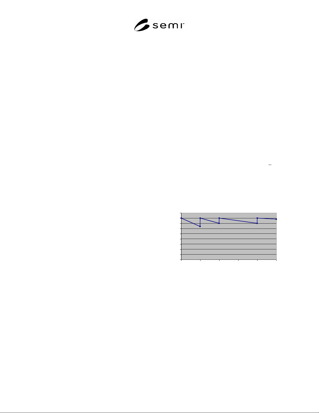
9.2.4 Hydrostatic Pressure Test Example
Hydrostatic Pressure Test Example
0
5
10
15
20
25
30
35
40
45
0 1530456075
Time (minutes)
Pressure (psig)
Figure 1
Hydrostatic Pressure Test Example
Test Media: Ultrapure Water
Test Media Temperature: 20C
Manufacturer’s maximum recommended operating
pressure: 40 psig.
Assembly is pressurized to 40 psig for 15 minutes.
Assembly is repressurized to 40 psig for 15
minutes.
Assembly is repressurized to 40 psig for 30
minutes.

SEMI E49.2-1104 © SEMI 1995, 2004 6
Assembly is repressurized to 40 psig.
During the next 15 minutes the Assembly pressure
is monitored to ensure that no visible leakage or
pressure loss in excess of 2 psi (5%) is observed.
9.2.5 As noted in Table 1, the requirement to pass this
test is no visible leakage and pressure decay of less than
5% of maximum recommended operating pressure.
The actual pressure decay and results of a visible
inspection should be noted on the test report.
9.3 Ultrapure Water Flush Test — This test consists of
resitivity and TOC tests and is required for every
Assembly shipped directly to an end user. These tests
may also be required periodically at other points in the
supply chain.
9.3.1 Resistivity Testing Recommendations
9.3.1.1 The test flow rate should be no less than the
manufacturer’s recommended minimum flow rate for
the instrument(s) being used. The test flow rate should
be no more than the maximum recommended flow for
the Assembly under test or the instrument(s) being
used.
9.3.1.2 Following recommended manufacturer
procedures, measure resistivity just prior to the
Assembly and at the Assembly outflow.
9.3.1.3 Allow the reading just prior to the Assembly to
stabilize until no change outside the precision of the
device is observed for at least 5 minutes and the
resistivity meets or exceeds the specification in section
7.2. Repeat the procedure at the Assembly outflow.
9.3.1.4 Temperature just prior to the Assembly must
not differ more than +/- 0.5 C when compared to the
temperature at the Assembly outflow. Otherwise, a
correction may need to be performed
9.3.1.5 Ensure that instrument connections are leak
tight to avoid positive bias from atmospheric CO
2
.
9.3.1.6 The inflow and outflow may be measured
simultaneously using a 2-channel/2-cell resistivity
meter.
9.3.1.7 As noted in Table 1, the requirement to pass
this test is a resistivity >
18 Mohm-cm @ 25°C (77°F)
and both inlet and outlet. The test report should include
inlet at outlet resistivity measurements.
9.3.2 TOC Testing Recommendations
9.3.2.1 The test flow rate should be no less than the
manufacturers recommended minimum flow rate for the
instrument(s) being used. The test flow rate should be
no more than the maximum recommended flow for the
Assembly under test or the instrument(s) being used.
9.3.2.2 Refer to ASTM Method D5997-96
(Reapproved 2000) when including UV persulfate
oxidation or ASTM 5173-97 when using UV without
persulfate. It should be noted which method is
incorporated.
9.3.2.3 Ensure that the instrument connections are leak
tight to avoid interference from atmospheric CO
2
.
Because TOC is determined by the difference of Total
Carbon (TC) and Total Inorganic Carbon (TIC), the
TOC detection limit can be no lower than 10% of the
TIC reading.
9.3.2.4 Allow the readings to stabilize until at least two
successive readings agree within +/- 5% and the TOC
adders are <
the value specified in Table 1.
9.3.2.5 The procedure should be performed just prior
to the Assembly and at the Assembly outflow.
9.3.2.6 As noted in Table 1, the requirement to pass
this test is TOC adders (ppb) of <
7.5. Both the inlet
and outlet TOC measurements should be included in the
test report.
9.4 Particle Testing Recommendations —
These tests
are required periodically to establish that the Assembly
design is typically capable of meeting the performance
criteria in Table 1.
9.4.1 The test flow rate should be no less than the
manufacturers recommended minimum flow rate for the
instrument(s) being used. The test flow rate should be
no more than the maximum recommended flow for the
Assembly under test or the instrument(s) being used.
9.4.2 Particle contribution will be determined without
valves being actuated. Active components such as
valves should be evaluated for particle performance at
the component level to supplement this test.
9.4.3 The water supplied to the Assembly under test
should be filtered with a maximum 0.05 micron filter
with a retention value such that filtered particle
concentration is <
10 particle/liter > 0.1 µm.
9.4.4 Particle contribution testing will measure the
Assembly outlet particle concentration and assumes all
particles are generated within the Assembly under test.
Periodic verification of the inlet particle concentration
specified in Section 9.4.3 should be performed and
reported in accordance with Section 9.1.1. Allowable
particle adders are outlined in Table 1.
9.4.5 Follow the manufacturer’s recommended
procedures for the optical particle counter.
9.4.6 Allow the reading to stabilize from rinse down
until there is no change within the expected noise for 2
or more intervals (i.e. no change in slope). An
appropriate sample interval should be chosen such that