semi合集-English.pdf - 第6854页
SEMI S2-0703a E © SEMI 1991, 2004 83 immediately achieve a safe co ndition. An FECS consists of sensors, logic system s and final elements as shown in Se ction R14-1 1. Replacing an existing electromechanical system with…

SEMI S2-0703a
E
© SEMI 1991, 2004 82
assessment and maintenance of suitable control
systems.
R14-7.2.3 The usage conditions and safety
performance should be determined by the finding of a
risk assessment as described in SEMI S10. Risk
assessment results can then be used to define
appropriate SIL levels and Categories.
NOTE 7:Emergency Off — Section 12.2.2 of SEMI S2 states
that the EMO system should consist of electromechanical
components. The exceptions give guidance to the design of
EMO circuits using alternative technologies. Regional,
national or industry standards may have additional
requirements (e.g., USA: ANSI/NFPA 79, Europe: EN
60204-1).
R14-7.2.4 Any deviation from the risk level of
electromechanical devices must be carefully evaluated
(see Section 8 of SEMI S2).
R14-7.2.5 Compliance with Section 12 of SEMI S2,
emergency shutdown will depend on the risk
assessment allowed in Section 8.3.11 of SEMI S2.
R14-7.3 Software and Programming
R14-7.3.1 The application software or function blocks
have to be verified before being used in an FECS. The
automation supplier usually provides a range of
approved software blocks.
R14-7.3.2 Access for programming of safety-related
functions should be restricted within the FECS to
trained people.
R14-7.3.3 To program or modify safety-related
programs or parts of it, specially trained or qualified
personnel are required. Any changes must be
documented and stored within the file history.
R14-8 Philosophy and General Concept
R14-8.1 Introduction — An automated machine
system mainly comprises components such as industrial
controller, drives, I/O etc. The level of safety
performance of equipment can differ depending on the
particular application of FECS. However, irrespective
of the particular application, the FECS always
comprises a series of sensors, logic elements and
actuators for safe shutdown or a motion into a safe and
stable machine state.
R14-8.1.1 The term FECS according to IEC 61508 Part
2, is equivalent to the terms SIS (safety instrumented
system) or SRS (safety related system) in other
application areas. The examples in this Related
Information show some possible architectures of the
logic system. Sensors, final elements and software are
discussed in this Related Information. Application
handbooks from automation suppliers provide users
with valuable information on how to use these
components in order to achieve a fail-to-safe,
equipment control system.
R14-8.1.2 For traditional semiconductor equipment,
non-safety-related and safety-related technology, are
separated. In many cases non-safety-related and safety-
related technology are linked, so that signals
representing diagnostics, enable, and feedback can be
exchanged.
R14-8.1.3 Main Characteristics of Architecture
Concepts
1. Fail-to-safe equipment control system with
conventional hardwired safety technology.
2. Fail-to-safe equipment control system with
separation between fail-to-safe and standard
network technology.
3. Fail-to-safe equipment control systems with
combined network technology for transmission
of fail-to-safe and standard data on a single
medium.
4. Redundancy can be used in all concepts to
increase availability. Different redundancy
concepts are in use (see R14-Section 9).
5. Visualization on the standard control part and
on the fail-to-safe part can be realized with
various interfaces on the standard part and on
the fail-to-safe part.
R14-8.2 Design of Architecture and Components
R14-8.2.1 Possible Application Areas
1. Semiconductor manufacturing industry
2. Guarding of people, machines, environment
and industrial processes
Emergency stop functions,
Emergency off functions,
Emergency shutdown functions,
Light gates,
Guard doors,
Scanners,
Motion control with safety functions,
Motor control with safety functions,
Process valves with safety functions, and
Process monitoring using safety-related interlocks.
R14-8.2.2 Safety-related Equipment Control System —
The design of FECS should be carried out in
accordance with IEC 61508 and applicable parts of the
other referenced standards. The safety controller is
used to control (open-loop) processes that can

SEMI S2-0703a
E
© SEMI 1991, 2004 83
immediately achieve a safe condition. An FECS
consists of sensors, logic systems and final elements as
shown in Section R14-11. Replacing an existing
electromechanical system with a safety controller does
not provide a safe system. Sensors and final elements
have to be considered as well.
R14-8.2.3 Safety Requirements – The FECS should be
suitable for SIL1 to SIL3 safety integrity level in
compliance with IEC 61508 or control categories 2 to 4
in compliance with ISO 13849-1 (EN 954-1). The
required safety performance requirements will be
determined in the system safety risk assessment. For
application assessment, local authorities and notified
bodies should request a safety handbook and
certification according to IEC 61508 or ISO 13849.
The safety-related system and its components should be
validated to ensure it fulfills the safety requirements
(SIL, CAT) determined from the risk analysis.
R14-8.2.4 Principle Of The Safety Functions — The
FECS executes safety functions to bring the equipment
into a safe state or to maintain it in a safe condition
when a hazardous event occurs. The safety function for
a production process can be realized using a user safety
function or a fault response function. The safe state can
be achieved by de-energizing the output modules.
R14-8.2.5 Communications — Non-safety-related and
safety-related communications between an industrial
controller and I/O modules should pass through a
standard network system or a safety network system in
sequence or through a combined network system (see
Figures R14-2-R14-7). Bridges, routers and repeaters
can be used in either standard networks or in safety
networks to adapt the network topology to the
individual layout of production process and equipment.
R14-8.3 Basic Topologies — Sections 7.3.1 through
7.3.3 describe examples of network-based architectures
that are capable of achieving a FECS. The suppliers
should take into account performance, timing, ease of
use, and other factors when selecting an architecture
type.
NOTE 8: These examples are not represented to be all-
inclusive.
SEMI S2-0703a
E
© SEMI 1991, 2004 84
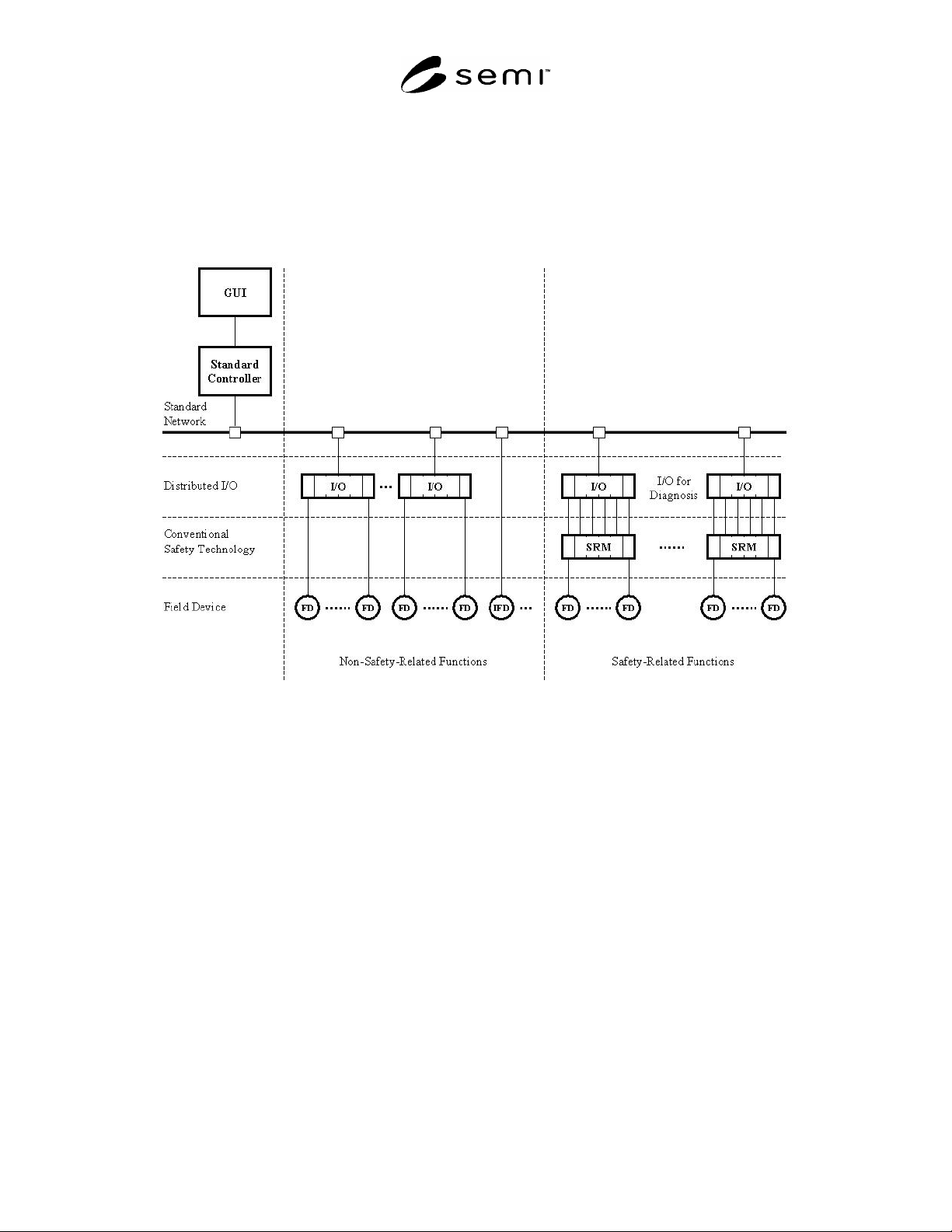
R14-8.3.1 Use of Fail-to-safe Equipment Control Systems with Conventional Safety Technology — Equipment
manufacturers can achieve functional safety by the use of hardwired circuits. Such hardwired circuits are realized
with terminals, electromechanical or electronic safety relays, and contactors. The relays would be certified for use
in CAT 4 applications according to ISO 13849. In Figure R14-2, a standard industrial controller is used with
standard I/O over a standard network to provide for the non-safety aspects of the machine and to provide diagnostics
and visualization of the hardwired safety functions.
Figure R14-2
Fail-to-safe Equipment Control System with Conventional Safety Technology