semi合集-English.pdf - 第6243页
SEMI G47-88 © SEMI 1988 10 NOTICE: T hese standards do n ot purport to address safety issues, if any, ass o ciated with their use. It is the responsibility of t he user of these standards to establish appropriate safety …
SEMI G47-88 © SEMI 19889
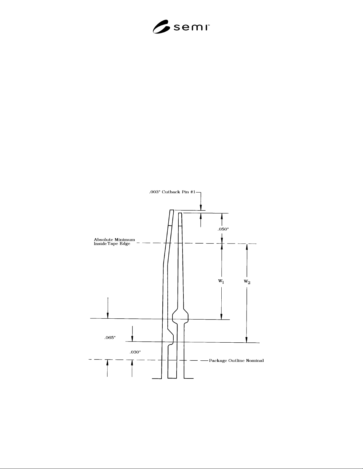
Table 4 (see Figure 7) Guidelines for Placement of Taping Dimensions 84 Lead Through 196 Leadframes
1. Nominal tape width maximum — 0.037"
2. Nominal tape width maximum — 0.060"
3. Tape width tolerance — ± 0.003"
4. Tape location tolerance — ± 0.015"
5. Absolute minimum location of outside tape edge from lead tip — 0.050".
6. Minimum location of outside tape edge from package outline nominal dimension — 0.065".
7. When window “W1” dimension cannot be met with minimum tape nominal width and recommended tolerancing
which is the case with various given pad sizes of different lead counts, window “W2” dimension, 0.030", from
package outline nominal should be used for the outside tape limit. If this window “W2” dimension still cannot be
met negotiation of tape width and location tolerances between supplier and purchaser is suggested to maintain
tape within the recommended window dimensions.
8. Recommended center line of tape for nominal location is midway between inside and outside tape edge limits for
window “W1” & window “W2” dimensions as appropriate and within tolerance limits.
9. Downset angle — 30°
10.Downsetting must begin inside 0.025" minimum flat distance along tie bar from inside edge of applied tape.
11.Recommended downset length is maximum allowable within the above guidelines.
Figure 7

SEMI G47-88 © SEMI 1988 10
NOTICE: These standards do not purport to address
safety issues, if any, associated with their use. It is the
responsibility of the user of these standards to establish
appropriate safety and health practices and determine
the applicability of regulatory limitations prior to use.
SEMI makes no warranties or representations as to the
suitability of the standards set forth herein for any
particular application. The determination of the
suitability of the standard is solely the responsibility of
the user. Users are cautioned to refer to manufacturer’s
instructions, product labels, product data sheets, and
other relevant literature respecting any materials
mentioned herein. These standards are subject to
change without notice.
The user’s attention is called to the possibility that
compliance with this standard may require use of
copyrighted material or of an invention covered by
patent rights. By publication of this standard, SEMI
takes no position respecting the validity of any patent
rights or copyrights asserted in connection with any
item mentioned in this standard. Users of this standard
are expressly advised that determination of any such
patent rights or copyrights, and the risk of infringement
of such rights, are entirely their own responsibility.
Copyright by SEMI® (Semiconductor Equipment and Materials
International), 3081 Zanker Road, San Jose, CA 95134. Reproduction o
f
the contents in whole or in part is forbidden without express written
consent of SEMI.

SEMI G48-89 © SEMI 1989, 1996 1
SEMI G48-89
SPECIFICATION FOR MEASUREMENT METHOD FOR MOLDED
PLASTIC PACKAGE TOOLING
1 Preface
This document is prepared to enable standard
measurement techniques to be used. It is intended that
the measurement techniques described in the
specification will apply to all molded plastic package
tooling, i.e. DIPS, SIPS, PCC, SO, Quad, and TAB.
2 Applicable Documents
2.1 SEMI Specifications
SEMI G14 — Plastic Molded DIP Tooling
SEMI G16 — Plastic Chip Carrier Tooling
SEMI G36 — Plastic Molded High Density TAB Quad
Tooling
SEMI G37 — Plastic Molded SO Package Tooling
3 Basic Equipment
3.1 The following basic equipment is required to
perform the specified measurements:
3.1.1 Toolmaker’s Microscope — 3× objective and
10× eyepiece total 30× with X and Y axes digital
readouts reading to 0.0001" . Minimum travel of stage
must be 2.0" × 2.0" . Eyepiece must be ± 0.0002"
minimum. The toolmaker’s microscope should have a
goniometer on the eyepiece as will as on the stage.
Accuracy of the goniometer shall be 0.1. The TM
microscope should have a Z axis with a digital
measurement capability, reading in increments of
0.0001" . The objective lens must be 20× minimum
which will give 0.0005" accuracy to the Z axis
measurements.
3.1.2 Optical Comparator — Surface illumination. 10"
minimum screen with 3" × 8" minimum travel.
Magnification of 10×, 20× minimum required.
Accuracy of 10× is 0.001" ; accuracy of 20× is 0.0005" .
Some operators may be able to improve on this
accuracy, but this is the best expected from average
inspectors.
3.1.2.1 Overlays at 20× may be used for rapid mea-
surement. The user is cautioned that the thickness of the
line must be controlled. Line widths must not exceed
0.010" in width, which will give an inaccuracy of
0.0005" in the measurement. Overlays must have the
datum marks clearly labeled. Overlays are tools which
speed inspection; however, rejects must be verified by
toolmaker’s microscope measurements, which are more
accurate.
3.1.3 Digital Depth Indicator — Mounted on a stand.
Digital reading with a range of 2" is available. Readout
must display increments of 0.0001" with ± 1 digit
accuracy.
3.1.4 Micrometer — 0 to 1.0" . 0.250" diameter for
measuring to 0.001" accuracy.
3.1.5 Eight (8) inch dial calipers for measuring to
0.002" accuracy.
3.1.6 Granite Surface Plate — Minimum size 18" ×
28" , with a surface accuracy of 0.0002" or better.
3.1.7 Surface Finish
3.1.7.1 Charmille Visual Surface Finish Standard —
(For comparison of Electric Discharge Machined
(EDM) surface only.)
3.1.7.2 Surface Comparator Standards — (For other
machined surfaces.)
3.1.7.3 Surface Analyzer
3.1.8 Binocular, Zoom Microscope — 10—15× mag-
nification with vertical or near vertical lighting.
3.1.9 Dial Indicators — With accuracy of .0001 and
with force not to exceed 5 grams.
3.2 Alternative Equipment — Sophisticated, automatic
equipment is not excluded from use, but the user must
ensure that such equipment meets or exceeds the
accuracy of the basic equipment so that correlation
problems may be avoided.
3.3 Calibration — All equipment to be calibrated on a
regular schedule.
4 Measurements
4.1 The following measurements will be made:
4.1.1 Package Thickness (Section 5.1)
4.1.2 Package Length (Section 5.2)
4.1.3 Package Width (Section 5.3)
4.1.4 Leadframe to Cavity Offset (Section 5.4)
4.1.5 Top Cavity Length (Section 5.5)
4.1.6 Top Cavity Width (Section 5.6)
4.1.7 Bottom Cavity Length (Section 5.7)