semi合集-English.pdf - 第4818页
SEMI C60-0305 © SEMI 2005 3 9.1.2.4 Stop watch. 9.1.2.5 6 mm (1/4 in) flexib le tubing. 9.1.3 Operating Procedure 9.1.3.1 Attach a suitable regu lator to the cylinder outlet. 9.1.3.2 Conn ect the flowmeter to the regulat…
SEMI C60-0305 © SEMI 2005 2
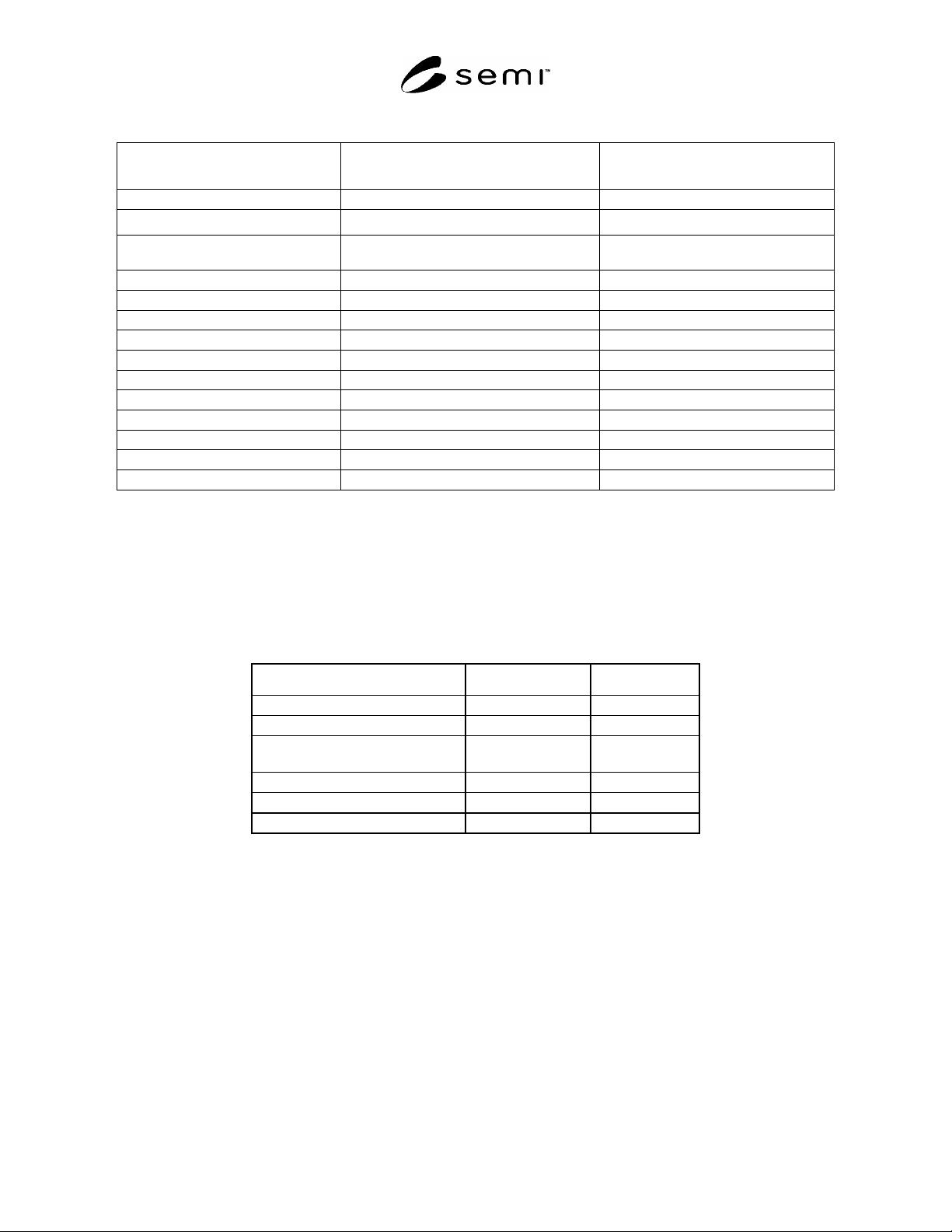
Table 1 Impurity and Other Requirements for Various Grades of Nitrous Oxide
Previous SEMI Reference #
C3.13-1000
(Specification)
C3.50-1000
(Guideline)
Grade 4.7 5.4
Purity 99.997%
#2,#3
99.9994%
#2, #3
Impurities Maximum Acceptable Level (ppm)
#1
Maximum Acceptable Level (ppm)
#1
Ammonia (NH
3
) 5 0.1
Carbon Dioxide (CO
2
) 2 0.5
Carbon monoxide (CO) 1 0.1
Hydrocarbons C
1
-C
5
1 0.1 (as C
1
)
Nitric Oxide (NO) 1 0.1
Nitrogen (N
2
) 10 3
Nitrogen dioxide (NO
2
) 1 0.1
Oxygen (O
2
) 2 N/A
Oxygen (O
2
) + Argon (Ar) N/A 0.5
Water (H
2
O) (v/v) 3 1.0
TOTAL SPECIFIED IMPURITIES 26 5.5
#1
An analysis of significant figures has not been considered. The number of significant figures is based on analytical accuracy and the precision
of the provided procedure.
#2
This specification applies to the gas phase of the cylinder as delivered.
#3
It is recommended that the user discontinue use of the cylinder prior to complete consumption of the liquid phase. The contents of cylinders
should be determined by weight, not pressure
8 Physical Constants
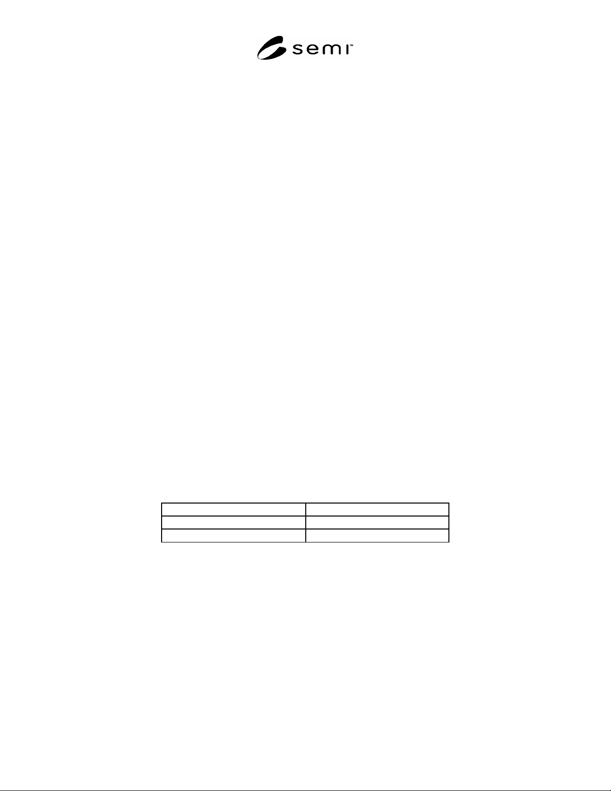
8.1 The physical constants of nitrous oxide are given in Table 2 (for information only).
Table 2 Physical Constants of Nitrous Oxide (for information only)
Metric Units US Units
Molecular weight 44.01 44.01
Boiling point at 1 atm 88.5°C 127.4°F
Density of gas at 70°F
(21.1°C) and 1 atm
1.947 g/L 0.1160 lb/ft
3
Specific gravity of gas 1.53 1.53
Critical pressure 71.46 atm 1052 psia
Critical temperature 36.4 °C 97.6°F
9 Analytical Procedures for Grade 4.7 Nitrous Oxide (See Appendix 1)
NOTE 1: Rapid withdrawal of gaseous nitrous oxide from a liquified source (e.g., cylinder) can result in a significant cooling
effect which may condense the nitrous oxide in the sampling lines.
9.1 Ammonia — This procedure is for the determination of ammonia in nitrous oxide using an apparatus employing
a detector tube filled with a color-reactive chemical.
9.1.1 Detection Limit — 0.2 ppm (mol/mol).
9.1.2 Apparatus
9.1.2.1 Pressure Regulator — Outlet Pressure Range 0–30 psig.
9.1.2.2 Flowmeter — Range 0–200 mL/min.
9.1.2.3 Detector Tube — Range 2–30 ppm.
SEMI C60-0305 © SEMI 2005 3
9.1.2.4 Stop watch.
9.1.2.5 6 mm (1/4 in) flexible tubing.
9.1.3 Operating Procedure
9.1.3.1 Attach a suitable regulator to the cylinder outlet.
9.1.3.2 Connect the flowmeter to the regulator using flexible tubing.
9.1.3.3 Open the cylinder valve and purge the flowmeter with nitrous oxide.
9.1.3.4 After the line is thoroughly purged, stop the flow of nitrous oxide and attach the detector tube to the outlet
of the flowmeter.
9.1.3.5 Start the flow of nitrous oxide and set the flow rate to 100 mL/min. The pressure and temperature of the
sample must be within the tolerances specified by the manufacturer.
9.1.3.6 Pass 100 mL of nitrous oxide through the detector tube.
9.1.3.7 Determine the concentration of ammonia according to the detector tube manufacturer’s instructions. The
concentration may not exceed the specification in Table 1 of this standard.
9.2 Carbon Monoxide and Carbon Dioxide — This procedure is for the determination of carbon monoxide and
carbon dioxide in nitrous oxide using a gas chromatograph with a flame ionization detector and methanizer with
back flush, (see Figure A1-1).
NOTE 2: In order to prevent nitrous oxide interference, a helium backflush to vent is needed for 3–5 times the analysis time
(estimated to be 3–5 minutes). Because nitrous oxide is converted into ammonia in the methanizer, stainless steel (ss) is required;
copper tubing and fittings are not used. The backflush removes the nitrous oxide from Column No. 1 preparing the column for
the next sample. Careful timing is required to identify carbon monoxide and carbon dioxide distinguishing both from the time
methane would appear, if present. Carbon monoxide and carbon dioxide are converted to methane in the methanizer; therefore,
both will be detected by the FID detector at the specific times determined by the analytical sequence of the standard.
9.2.1 Detection Limit — 1 ppm (mol/mol), (50 ppb depending on conditions).
9.2.2 Instrument Parameters
9.2.2.1 Columns: Column 1: Porapak QS, 4.6 m (15 ft) by 5 mm (3/16 in) or equivalent. Column 2: Molecular
sieve 5A, 1.97 m (6 ft) by 5 mm, 80/100 mesh (reference only) or equivalent.
9.2.2.2 Carrier Flow: 30 mL/min helium.
9.2.2.3 Sample Volume: 0.5 to 2.0 mL.
9.2.2.4 Temperatures:
Detector 35°C
Column Oven 35°C
Methanizer 500°C
9.2.3 Calibration Standard — 1–5 ppm (mol/mol) carbon monoxide, 1–5 ppm (mol/mol) carbon dioxide, balance
nitrous oxide.
9.2.4 Operating Procedure
9.2.4.1 Inject the calibration standard into the column using a gas sampling valve. Record the retention times and
peak areas. The order of elution is carbon monoxide, methane, carbon dioxide, and nitrous oxide. Back flush 18
minutes.
9.2.4.2 Inject the sample to be tested in same manner as the calibration standard. Record the retention times and
peak areas.
9.2.4.3 Repeat ¶9.2.4.1.
SEMI C60-0305 © SEMI 2005 4
9.2.4.4 Compare the average peak areas of the calibration standard to that of the nitrous oxide sample being tested.
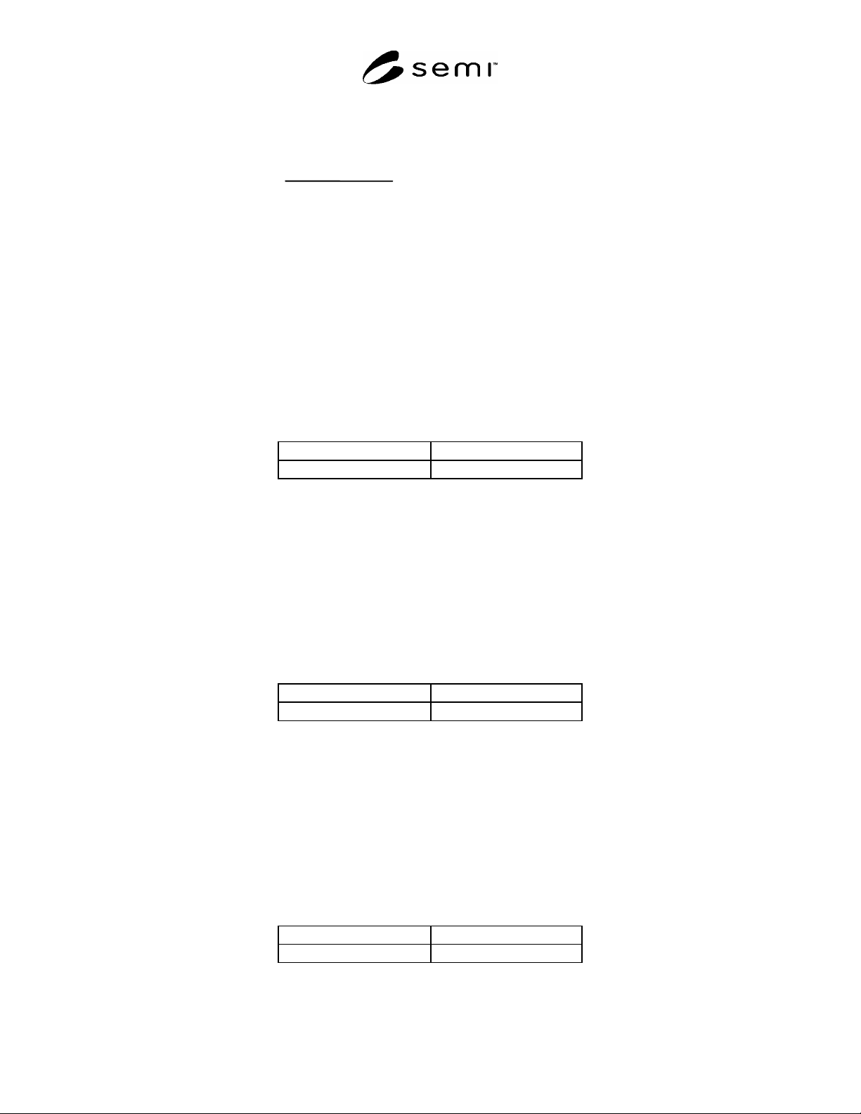
Calculate the concentrations of carbon monoxide and carbon dioxide, using the formula below. The result may not
exceed the specification in Table 1 of this Standard.
Sample Pea
k
Area
Standard Peak Area
Concentration
of Standard
Concentration
of Sample
9.3 Hydrocarbons C
1
– C
5
— This procedure is for the determination of hydrocarbons C
1
– C
5
in nitrous oxide
using a gas chromatograph with a flame ionization detector.
9.3.1 Methane Determination
9.3.1.1 Detection Limit — 0.1 ppm (mol/mol).
9.3.1.2 Instrument Parameters
9.3.1.2.1 Column: 5A molecular sieve, 1.9 m (6 ft) by 6.4 mm (1/4 in) OD by 5.3 mm (0.210 in) ID stainless steel
or equivalent.
9.3.1.2.2 Carrier Flow: 25 mL/min helium.
9.3.1.2.3 Sample Volume: 5.0 mL.
9.3.1.2.4 Temperatures:
Detector 150°C
Column Oven 30°C
9.3.2 Ethane Determination
9.3.2.1 Detection Limit — 0.3 ppm (mole/mole).
9.3.2.2 Instrument Parameters
9.3.2.2.1 Column: Porapak Q, 1.9 m (6 ft ) by 6.4 mm (1/4 in) OD by 5.3 mm (0.210 in) ID stainless steel or
equivalent.
9.3.2.2.2 Carrier Flow: 50 mL/min helium.
9.3.2.2.3 Sample Volume: 1.0 mL.
9.3.2.2.4 Temperatures:
Detector 150°C
Column Oven 60°C
9.3.3 Ethylene, Propane, Acetylene, Propylene, n-butane, and n-pentane Determination
9.3.3.1 Detection Limit — 0.1 ppm (mole/mole).
9.3.3.2 Instrument Parameters
9.3.3.2.1 Column: Phenylisocyanate/Porasil C, 3 m (10 ft) by 4.8 mm (3/16 in) OD by 3.7 mm (0.147 in) ID
stainless steel or equivalent.
9.3.3.2.2 Carrier Flow: 25 mL/min helium.
9.3.3.2.3 Sample Volume: 1.0 mL.
9.3.3.2.4 Temperatures:
Detector 150°C
Column Oven 30°C