semi合集-English.pdf - 第2131页
SEMI E54.15-0305 © SEMI 2005 3 5.2.4 ISO — Inter national Stan dards Organization 5.2.5 MAC — Media Access Control 5.2.6 NCS — Network Com munication Standar d 5.2.7 OCS — Object Communications Specification 5.2.8 OSI — …

SEMI E54.15-0305 © SEMI 2005 2
NOTICE: This standard does not purport to address safety issues, if any, associated with its use. It is the
responsibility of the users of this standard to establish appropriate safety and health practices and determine the
applicability of regulatory or other limitations prior to use.
3 Limitations
3.1 This document specifies a semiconductor equipment SAN based solely on SafetyBUS p and is a companion
document to the Object Communication Specification for the SafetyBUS p Protocol; thus a complete specification
of this standard necessarily includes the SafetyBUS p protocol specifications. There are other semiconductor
equipment SAN communications options. The specifications for these options are not included.
3.2 This standard specifies enhancements that provide additional capabilities over and above those currently
required by SafetyBUS p. In order to avoid document consistency problems, information in the Object
Communication Specification for the SafetyBUS p Protocol that relate to this standard is not repeated in this
document. This document is limited to describing enhancements or limitations to the SafetyBUS p specifications
that are imposed by this standard specification.
4 Referenced Standards
4.1 SEMI Standards
SEMI E39 — Object Services Standard: Concepts, Behavior, and Services (OSS)
SMI E54 — Sensor/Actuator Network Standard
SEMI E54.1 — Standard For Sensor/Actuator Network Common Device Model
SEMI E54.3 — Specification For Sensor/Actuator Network Specific Device Model For Mass Flow Device
SEMI E54.10 — Specification For Sensor/Actuator Network Specific Device Model For An In-Situ Particle
Monitor Device
SEMI E54.11 — Specification For Sensor/Actuator Network Specific Device Model For An Endpoint Device
4.2 ISO Standards
1
ISO 7498 — Basic Reference Model for Open Systems Interconnection
4.3 SafetyBUS p Club International
2
Specification — Object Communication Specification (OCS) for the SafetyBUS p Protocol Version 1.1
April 09, 2004 may be accessed on the SafetyBUS p Club International web site http://www.safetybus.com/semi/
Reference Guide — Pilz Automation Technology – Guide to Programmable Safety Systems, February 2002
Volume 2, 1
st
Edition
NOTICE: Unless otherwise indicated, all documents cited shall be the latest published versions.
5 Terminology
5.1 Terminology that is common to all of the documents in this SAN standard may also be defined in the Sensor
/Actuator Network Standard (see reference SEMI E54 ¶4.1). Terminology may be reproduced here which is defined
in other SEMI documents.
5.2 Abbreviations and Acronyms
5.2.1 CAN — Controller Area Network
5.2.2 CDM — Common Device Model
5.2.3 DM — Device Manager (object)
1 International Organization for Standardization, ISO Central Secretariat, 1, rue de Varembé, Case postale 56, CH-1211 Geneva 20, Switzerland.
Telephone: 41.22.749.01.11; Fax: 41.22.733.34.30, Website: /www.iso.ch
2 SafetyBUS p Club International Partner Association, Robert-Bosch-Str. 30, 73760 Ostfildern, Germany ,Telephone (+49) 711 3409-118, Fax:
(+49) 711 3409-449, website: www.safetybus.com
SEMI E54.15-0305 © SEMI 2005 3
5.2.4 ISO — International Standards Organization
5.2.5 MAC — Media Access Control
5.2.6 NCS — Network Communication Standard
5.2.7 OCS — Object Communications Specification
5.2.8 OSI — Open Systems Interconnect
5.2.9 SAC — Sensor, Actuator, Controller (Object)
5.2.10 SAN — Sensor/Actuator Network
5.2.11 SDM — Specific Device Model
5.3 Device Component Definitions
5.3.1 As this standard specification defines the presentation or mapping of CDM data structure and behavior over a
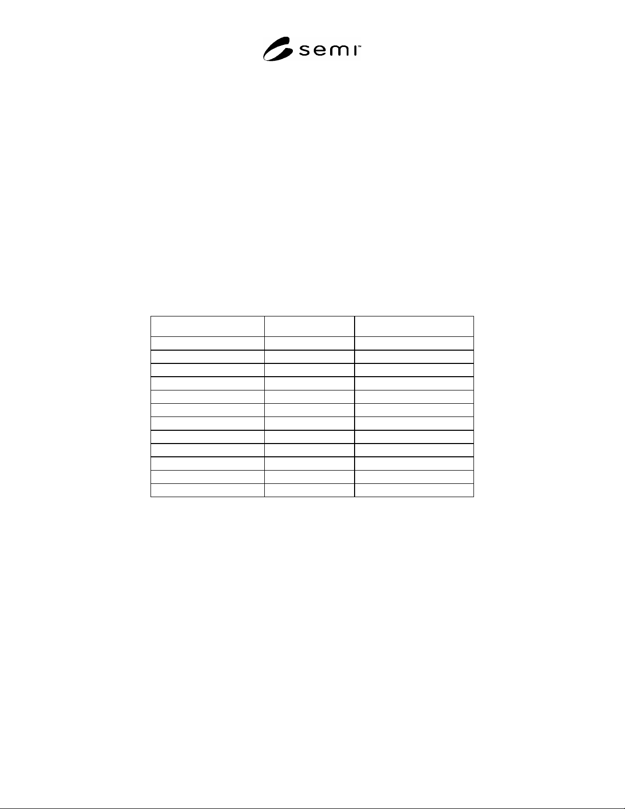
network, it makes use of many of the terms in the SEMI E54.1 CDM document. Table 1 provides a mapping of
fundamental terminology of the CDM document into this document and the SafetyBUS p standard specifications.
Note that Column 2 contains an equal sign “=” if the definition is used exactly as specified in the CDM
specification.
Table 1 Mapping of Common Device Model to NCS Terminology
CDM Term NCS Equivalent SafetyBUS p Equivalent
Device = =
Device Model = =
Class = Server Class
Object =, Class, Instance =, Server Class, Instance
Instance = =
Attribute = =
Behavior = =
Service = =
State Diagram = =
Byte = =
Nibble = =
Character String = =
5.4 SafetyBUS p Specific Definitions
5.4.1 Server Class — subset of devices that offer similar functions and provide fixed defined functionality in a
uniform way.
5.4.2 master/slave — communication over a SafetyBUS p network provides exclusive control of data by a “master”
or “host” device. All network input data is reported exclusively to the host when requested by the host, and the host
has exclusive control over the states of all network output signals of all nodes acting as its “slaves”. Master/Slave
communication provides the typical request/response oriented network communications.
5.4.3 peer-to-peer — On SafetyBUS p networks, messages formatted according to the SafetyBUS p protocol are
embedded into the SafetyBUS p packet structure that is used on the CAN network. The SafetyBUS p protocol over
CAN supports the asynchronous or unsolicited bi-directional transmission of data between nodes. This type of
communication is referred to as peer-to-peer.
5.4.4 SafetyBUS p — an open protocol maintained by Pilz GmbH & Co and distributed by SafetyBUS p Club
International as a reliable and standard means of interconnection for simple field devices. The SafetyBUS p
standard wraps a communication model and protocol as well as CAN specifications for OSI reference model layers
1 and 2, to provide a complete network definition. The OSI reference model layer 7 specifies the application layer.
SEMI E54.15-0305 © SEMI 2005 4
6 Communication Protocol High Level Structure
6.1 The SafetyBUS p protocol is loosely based on three layer architecture. These three layers constitute a collapsed
form of the seven layer OSI architecture which map into the physical, data link, and application layers of the OSI
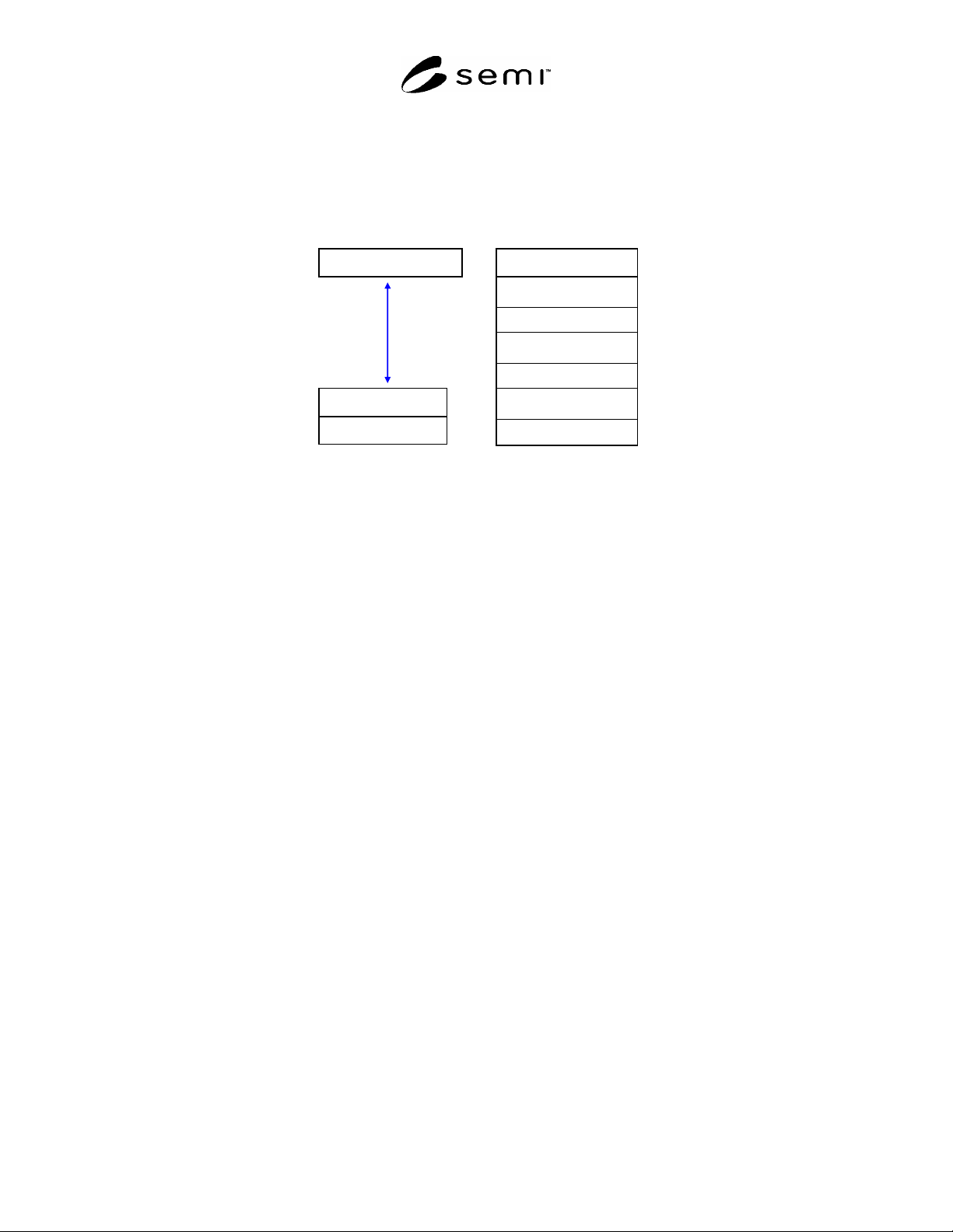
Basic Reference Model (see ¶4.2). The high-level protocol architecture is shown in Figure 1.
Application Layer
Physical Layer
Data Link Layer
Physical Layer
Data Link Layer
Network Layer
Transport Layer
Session Layer
Presentation Layer
Application Layer
Layered View of SafetyBUS p
OSI Reference Model
Figure 1
Layered View of SafetyBUS p
6.1.1 Note that Figure 1 represents a conceptual view of the technology architecture. Conforming implementations
must implement the services defined in this specification at each layer and must appear (from the network) to have
implemented this architecture, however an internal modular partitioning is not required. Implementations may
sacrifice modularity in order to achieve high performance.
6.1.2 The application layer is specified in the SafetyBUS p OCS (see reference ¶4.3) and provides for the definition
of SafetyBUS p applications as a collection of addressable objects. A subset of these objects may be addressed over
the network (as defined by the implementation).
6.1.3 In the remainder of this section the protocol structure is described in more detail in terms of the OSI seven
layer reference model, the object model environment and network management specifications.
6.2 Physical Layer — The device shall comply with a physical layer specification identified in the Controller Area
Network (CAN) specification. Physical layer specification includes physical signaling (levels and data rates),
transceivers, node isolation, media topology, cable specifications, network connectors and taps, and power
considerations (load limits, system tolerances, and power supply options).
6.3 Data Link Layer — The device shall comply with a data link layer specification the Controller Area Network
(CAN) specification. Data link layer specification includes the media access control mechanism and the logical link
control mechanism.
6.4 Network Layer — There is no distinct Network layer.
6.5 Transport (Messaging) Layer — There is no distinct Transport layer.
6.6 Session Layer — There is no distinct Session layer.
6.7 Presentation Layer — There is no distinct Presentation layer.
6.8 Application Layer — The device shall comply with the SafetyBUS p application layer specification for defining
and addressing objects, including their attributes and services, and enabling specified network behavior. The device
shall comply with the object messaging and object model specifications included in the SafetyBUS p OCS. In
addition the device shall comply with the object specifications defined in §7 of this document.
6.8.1 Object Models — The SafetyBUS p protocol includes an object-oriented specification for addressing objects
explicitly, including their attributes and services, and communicating object attributes in an application dependent
format. The device shall comply with the object messaging and object model specifications included in the