semi合集-English.pdf - 第4394页
SEMI F97-0305 © SEMI 2005 4 FMCS Level: consists of the FMCS, FPU Control Level: consists of the FPU that are monitored and controlled by the FMCS, and FPU Field Le vel: consists of the ha rdware com ponents to mon…

SEMI F97-0305 © SEMI 2005 3
5.2.4 data cache — unit within an IT system or FMCS being responsible for buffering data usually with the focus
of performance optimization.
5.2.5 facility monitoring and control system (FMCS) — IT System consisting of software and hardware components
that are used to monitor and control all FPUs as described in §2 . Typically a FMCS is implemented using a PC
based architecture. A FMCS in general consists of the following sub components:
Software modules to monitor and control the FPU,
Software module to cover alarm&event history,
Report archive to store reports persistently,
Data archive to store monitored data persistently,
Human interface to provide access for human users to FMCS functionality, and
Communication infrastructure to connect to the different FPUs and to external systems (e.g. Manufacturing
Execution System, Enterprise Resource Planning System).
5.2.6 facility system — describes an overall architecture in the context of facility monitoring and control. A Facility
System typically consists of 4 layers as described in §2.
5.2.7 FPU Control Level — describes a unit to monitor and/or control a certain piece of facility infrastructure. A
FPU owns a well defined interface that enables external IT systems to monitor (and control) activities running on the
specific FPU.
5.2.8 FPU Field Level — describes a unit of a FPU, such as sensors, actuators, aggregates or even an own
subcontrol level to control a certain piece of facility infrastructure in order to support all the necessary functions of
the FPU at the control level.
5.2.9 integration — covers the interconnection of FMCS and FPUs by Engineering and Commissioning with
respect to communication. It does not cover the Engineering and Commissioning of the FPUs themselves.
5.2.10 network — general term for a bus technology which includes field bus technology or local area networks.
5.2.11 programmable logic controller (PLC) — a system consisting of software and hardware usually to fulfill
monitor and control tasks. Typically a PLC comprises the following components:
rack — accommodates the modules and connects them to each other;
power supply — provides the internal supply voltages;
central processing unit (CPU) — stores and processes the user program;
signal modules — adapt the signals from the system to the internal signal level or control actuators via digital
and analog signals;
function modules — execute complex or time-critical processes independently of the CPU; and
communication processors — interface the programmable controllers to each other or to other devices via a
network.
5.2.11.1 A PLC may consist of several racks which are linked to one another via bus cables or may all be self
contained.
5.2.12 Tag — is a unique identifier within a FMCS to access information in a FPU. Assigned to each unique Tag is
the data necessary to select the access to a particular FPU on the Network and to access the particular information
within that FPU.
6 Overview
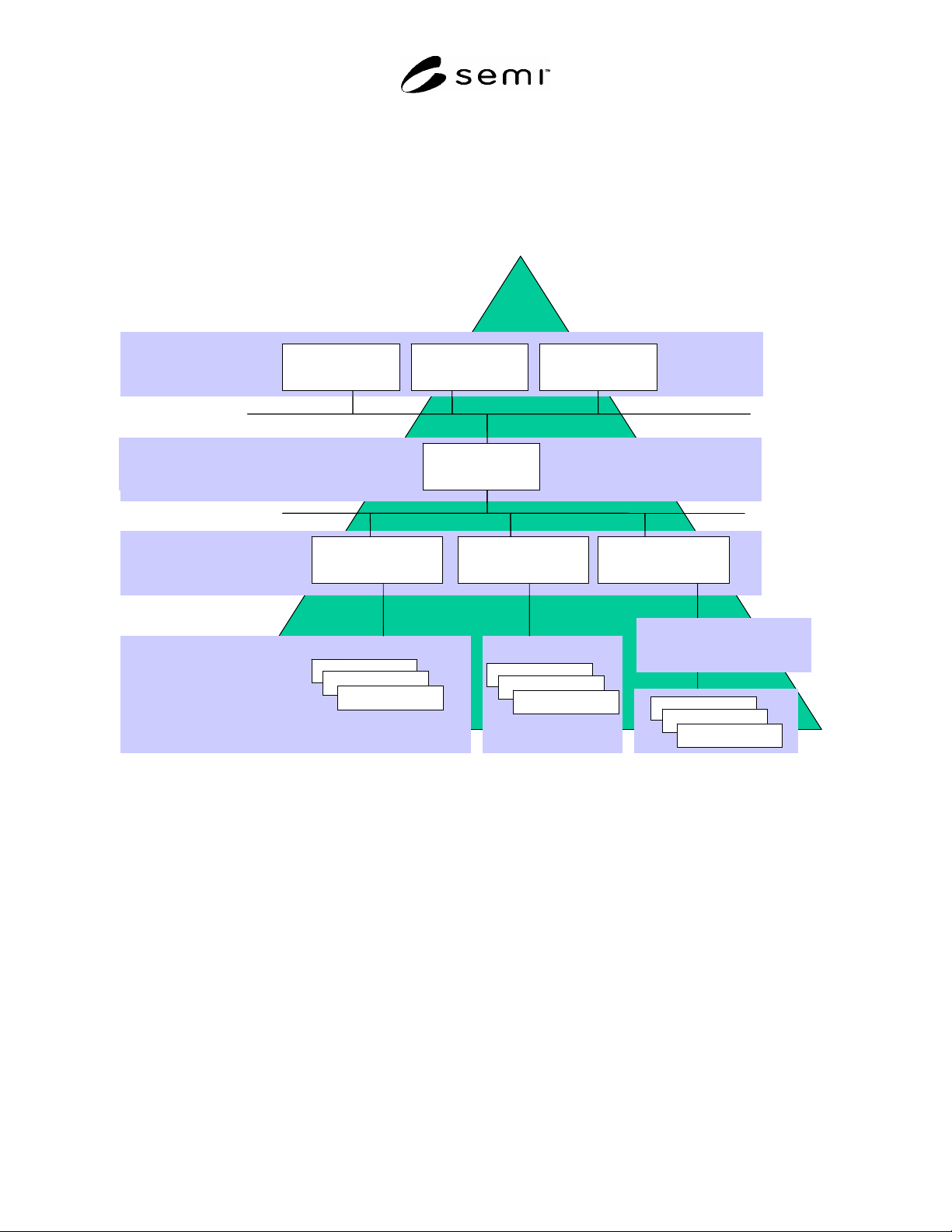
6.1.1 A facility system within this standard is described by four levels (see Figure 1).
ERP/MES Level: consists of systems within the Enterprise Resource Planning and Manufacturing Execution
System,
SEMI F97-0305 © SEMI 2005 4
FMCS Level: consists of the FMCS,
FPU Control Level: consists of the FPU that are monitored and controlled by the FMCS, and
FPU Field Level: consists of the hardware components to monitor and control the FPUs. A subcontrol level
within the level of the FPU may or may not be present depending on the complexity of the functions to be
performed.
FMCS
HVAC
FPU 1 FPU 2
...
FPU n
FMCS Level
FPU
Control
Level
FPU
Field
Level
I/O
I/O
I/O
I/O
ERP / MES Level
ERP
MES …
FMCS
HVAC
FPU 1
Ultra Pure Water
FPU 2
...
FPU n
FMCS Level
FPU
Control
Level
FPU
Field
Level
I/O
ERP / MES Level
I/O
I/O
I/O
I/O
I/O
Subcontrol level
Subordinated
unit n
I/O
I/O
I/O
ERP
MES …
Figure 1
Facility System
SEMI F97-0305 © SEMI 2005 5
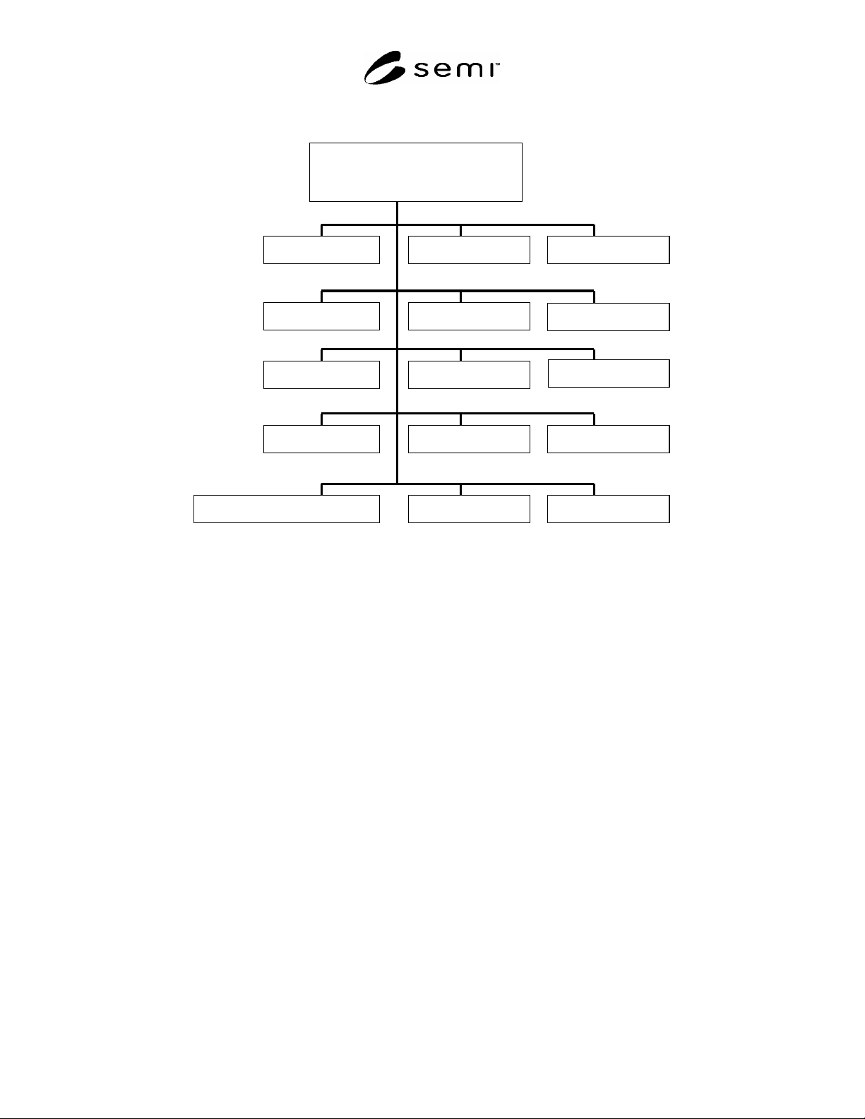
6.1.2 Figure 2 depicts typical examples of Facility Package Units.
Facility Monitoring and
Control System
Cleanroom
Electrical
Building systems
HVAC
Chilled water
Exhaust
Hot water
Fire protectionCompressed air
Ultra pure water
Chemicals
Gases
Waste water treatment
...
Life safety
Facility Monitoring and
Control System
Cleanroom
ElectricalElectrical
Building systems
HVAC
Chilled water
Exhaust
Hot waterHot water
Fire protectionFire protectionCompressed airCompressed air
Ultra pure water
ChemicalsChemicals
GasesGases
Waste water treatment
......
Life safetyLife safety
Figure 2
Typical Examples of Facility Package Units
6.1.2.1 Description of Figure 2.
Building systems — facility installation concerning the building, e.g. lighting.
Chemicals — facility installation for the supply of chemicals, e.g. for process tools.
Chilled water system — facility installation for the supply of cold water, e.g. for air condition or process tools.
Cleanroom — production area with clean conditions and specifications concerning air condition.
Compressed air — facility installation for the supply of compressed air.
Electrical — facility installation for the electrical power supply.
Exhaust — facility installation for the disposal of gases and contaminated air.
Fire protection — facility installation for fire protection, e.g. for fire and smoke detection.
Gases — facility installation for the supply of bulk or special gases, e.g. for process tools.
Hot water — facility installation for the supply of hot water, e.g. for radiators, air condition or process tools.
HVAC — facility installation for heating, ventilation and air conditioning.
Life safety — facility installation for life safety and security, e.g. for detection of leakages of gases.
Ultra pure water — facility installation for the supply of ultra pure water, e.g. for process tools.
Waste water treatment — facility installation for the treatment of waste water.