semi合集-English.pdf - 第4716页
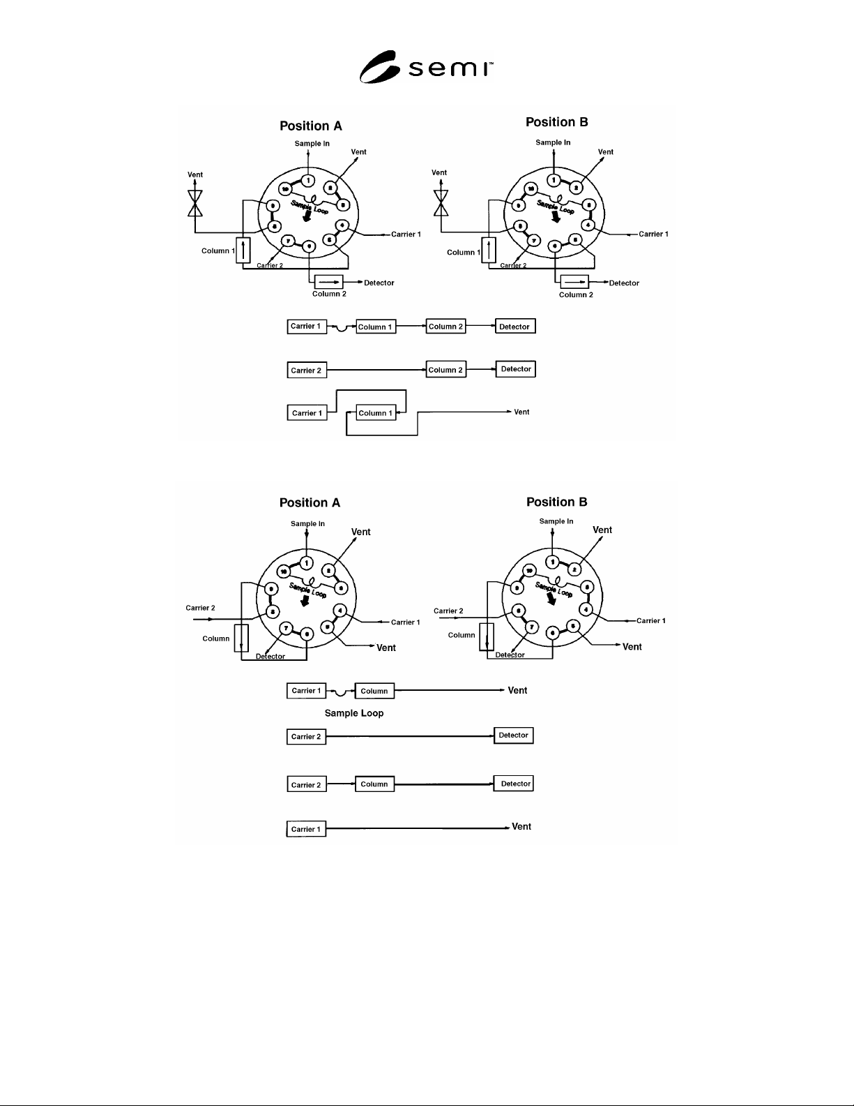
SEMI C3.23-1000 © SEMI 1984, 2004 5 Figure 1 Figure 2

SEMI C3.23-1000 © SEMI 1984, 2004 4
4.6.2 Flow Requirements
4.6.2.1 High purity, hydrocarbon-free (less than 0.1
ppm) hydrogen, 35–40 mL/min or 40% hydrogen in
either helium or nitrogen at 75–80 mL/min.
4.6.2.2 Dry, hydrocarbon-free (less than 0.1 ppm) air,
350 mL–400 mL/min.
4.6.2.3 Set sample flow rate in accordance with the
instrument manufacturer’s instructions.
4.6.3 Calibration Standards
4.6.3.1 Zero oxygen with a known quantity of
hydrocarbons of approximately 0.1 ppm.
4.6.3.2 Upper level balance oxygen span gas of not
more than five times the concentration specified in
Section 2 of this Standard.
4.6.4 Operating Procedure
4.6.4.1 Do not change initial flow settings for
hydrogen, air and sample once established.
4.6.4.2 Introduce the zero oxygen with a known
quantity of hydrocarbons and, using the 0–1 ppm range,
set the output to read the correct level, using the zero
adjust knob.
4.6.4.3 Introduce the span gas standard in oxygen and,
using the span adjust knob, set the output to the level in
the span gas.
4.6.4.4 Introduce the oxygen sample into the analyzer
and read the quantity of hydrocarbons on the analyzer.
The result may not exceed the specification in Section 2
of this standard.
4.7 Water — This procedure is for the determination
of trace moisture (water) in oxygen using a continuous
flowing, cooled-surface condensation, dewpoint/frost-
point hygrometer. (See Note 9.)
4.7.1 Detection Limit — 0.6 ppm (vol/vol) at -79°C (-
100°F)
4.7.2 Flow Requirements
4.7.2.1 Set sample flow rate and pressure in
accordance with the instrument manufacturer’s
instructions.
4.7.3 Calibration Standard — A calibration ther-
mometer designed to indicate temperatures in the -79°C
(100°F) range is required.
4.7.4 Operating Procedure
4.7.4.1 An appropriately cleaned stainless steel or
copper sampling line must be used. If it has been
exposed to ambient moisture, it must be purged with
dry gas prior to use.
4.7.4.2 Flow the sample gas through the hygrometer
until the sampling system and instrument have reached
equilibrium with the gas.
4.7.4.3 After equilibrium has been reached, cool the
mirror of the hygrometer, as specified by its
manufacturer, to determine the dewpoint/frostpoint of
the sample gas.
4.7.4.4 Verify the dewpoint/frostpoint reading for at
least 30 minutes after it becomes stable.
4.7.4.5 Correct the dewpoint/frostpoint reading to 1
atm pressure. Convert it to ppm (vol/vol) using an
appropriate table. The result may not exceed the
specification in Section 2 of this standard.
4.8 Notes
Note 1: Introduce the calibration standard as many
times as necessary to achieve the desired precision.
Note 2: All gases used in the analysis of the sample
should not contain more than 10% of the specified
value of the component of interest, unless otherwise
stated.
Note 3: A flow restrictor should be installed on the vent
from port 8 to match the pressure drop of the detector.
Note 4: A flow controller is required on each carrier
inlet.
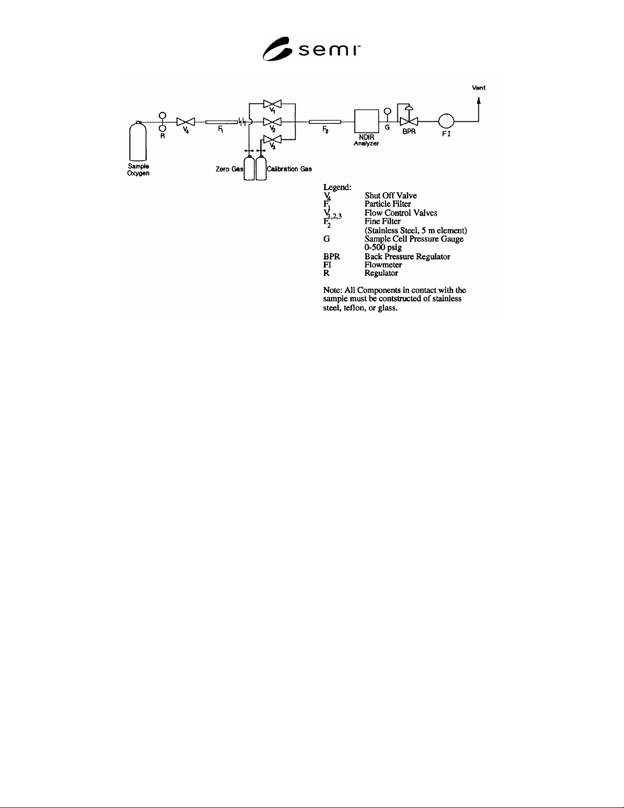
Note 5: An example of an operating procedure is
outlined below for the sample system shown in Figure
1. This procedure is appropriate only when the infrared
gas cell is designed to withstand the 200 psig sample
pressure.
Note 6: Operating procedures for other non-dispersive
infrared analyzers vary depending on manufacturer.
Refer to individual instrument vendor instructions in
each case.
Note 7: As the flow rate and heat capacity of the matrix
gas affect the instrument output, the zero and span gas
matrices must coincide with that of the sample gas.
Note 8: The effective response of a flame ionization
detector-equipped total hydrocarbon analyzer can vary
among different hydrocarbons and must be
approximated. However, the response of the most
common hydrocarbon impurities can be accurately
totaled and compared to methane.
Note 9: The sampling system and hygrometer must be
designed to operate at the sample pressure, or the
sample pressure must be reduced by a regulator with a
diaphragm of stainless steel or other suitable material.
SEMI C3.23-1000 © SEMI 1984, 2004 5
Figure 1
Figure 2
SEMI C3.23-1000 © SEMI 1984, 2004 6
Figure 3
Sample System for NDIR Analyzer
NOTICE: These standards do not purport to address safety issues, if any, associated with their use. It is the
responsibility of the user of these standards to establish appropriate safety and health practices and determine the
applicability of regulatory limitations prior to use. SEMI makes no warranties or representations as to the suitability
of the standards set forth herein for any particular application. The determination of the suitability of the standard is
solely the responsibility of the user. Users are cautioned to refer to manufacturer’s instructions, product labels,
product data sheets, and other relevant literature respecting any materials mentioned herein. These standards are
subject to change without notice.
The user’s attention is called to the possibility that compliance with this standard may require use of copyrighted
material or of an invention covered by patent rights. By publication of this standard, SEMI takes no position
respecting the validity of any patent rights or copyrights asserted in connection with any item mentioned in this
standard. Users of this standard are expressly advised that determination of any such patent rights or copyrights, and
the risk of infringement of such rights, are entirely their own responsibility.
Copyright by SEMI® (Semiconductor Equipment and Materials
International), 3081 Zanker Road, San Jose, CA 95134. Reproduction of
the contents in whole or in part is forbidden without express written
consent of SEMI.