semi合集-English.pdf - 第1431页
SEMI 30.1-0200 © SEMI 1998, 2000 6 are comm o n to all three types of ISEM eq uipment. The WORKING state i s differen t for each type of equipment. The sa me state nam es a nd transition identifiers are used to identify …

SEMI 30.1-0200 © SEMI 1998, 20005
5.2.29 material — a piece or pieces of substrate, one
or more substrates, a lot, a batch, or a run.
5.2.30 metrology equipment — any equipment that
collects and reports information on specific
predetermined locations or features on a substrate with
consistent data structure or that reports general
information about the entire substrate.
5.2.31 notch — a U-shaped cut on the edge of a
substrate that is commonly located with respect to a
specific crystal plane.
5.2.32 overlay — the actual distance between two
features on different layers of a substrate, compared to
the expected distance.
5.2.33 pattern — 1) The physical features on a
substrate surface. 2) An ideal pattern is the arrangement
of features expressed in a calculated or mathematical
manner.
5.2.34 pattern element — 1) Any recognizable set of
features. 2) A rectangular sub-unit of a pattern or a
pattern element. There may be multiple levels of pattern
elements.
5.2.35 primary fiducial — a key characteristic of a
substrate used to align the substrate during processing
(such as a notch or major flat).
5.2.36 region — a single field of view which may be a
collection of sites.
5.2.37 registration — the actual distance between two
features on the same layer of a substrate, compared to
the expected distance.
5.2.38 reticle — a mask that contains the patterns to
be reproduced on a substrate; the image may be equal to
or larger than the final projected image.
5.2.39 review — the process of classification of
anomalies which may result in the appending of
additional data to inspection data. Used to create a field
on a substrate.
5.2.40 review equipment — equipment that accepts
information about anomalies on a substrate, gathers
information on those anomalies, and reports that data.
5.2.41 run (noun) — the material processed during the
EXECUTING state.
5.2.42 run (verb) — the actions of a process between
the READY state and the STOPPING state.
5.2.43 safe state — a state in which the equipment
presents no danger to the product or user. This implies
that safety interlocks are in place such that the
equipment can be serviced without harm to the operator
and that the material being processed has been removed
from the processing station into an accessible location.
5.2.44 site — a single x,y coordinate where an action
can be performed (e.g., alignment or review). The area
associated with a site is determined by the equipment
accuracy (e.g., optics, stage algorithms).
5.2.45 slot — a physical location within a Carrier
capable of containing a substrate. Also referred to as a
carrier location.
5.2.46 substrate — the basic unit of material,
processed by semiconductor equipment, such as wafers,
CDs, flat panels, or masks.
6 Communication Requirem ents
6.1 It is required that any ISEM-compliant equipment
follow the Communications State Model in SEMI E30.
In addition, ISEM-compliant equipment shall support
the High Speed Messaging Service Standard (SEMI
E37/HSMS). It is a minimum requirement to support
Single Session (SEMI E37.1/HSMS-SS) sending
SECS-II messages over TCP/IP. The reason behind this
requirement is the size of the process programs used by
this class of equipment and the amount of data
produced.
7 State Models
7.1 Processing State Model Requirements
7.1.1 The processing state model included in this
standard is a requirement for ISEM equipment. This
standard requires implementation of all SEMI E30 state
models (such as control, communication, and on-
line/off-line). A state model consists of state model
diagrams, state definitions, and a state transition table.
All state transitions in this standard, unless otherwise
specified, shall correspond to collection events.
7.1.2 A state model is the host’s vie w of the
equipment and does not necessarily describe the
internal equipment operation. All ISEM state model
transitions shall be mapped sequentially into the
appropriate internal equipment events that satisfy the
requirements of those transitions. In certain
implementations, the equipment may enter a state and
have already satisfied all of the conditions required by
the ISEM state model for transition to another state.
The equipment makes the required transition without
any additional actions in this situation.
7.1.3 Some equipment may need to include additional
states other than those in this standard. Additional states
may be added but shall not change the ISEM-defined
state transitions. All expected transitions between ISEM
states shall occur.
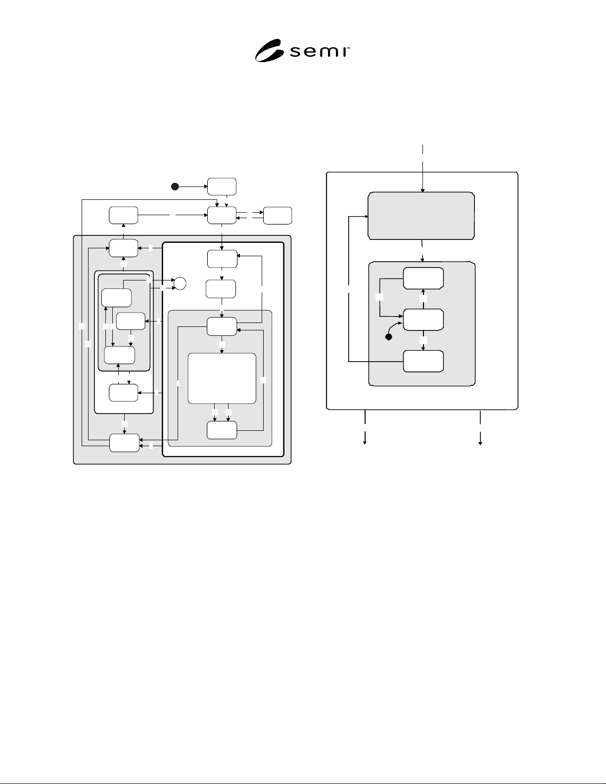
7.2 Processing State Model Diagram — Processing
state models are detailed for ISEM equipment in Figure
1. This diagram contains all states and transitions that
SEMI 30.1-0200 © SEMI 1998, 2000 6
are common to all three types of ISEM equipment. The
WORKING state is different for each type of
equipment. The same state names and transition
identifiers are used to identify common states and
transitions of the three types of equipment. The
working states for the three types of equipment are
presented in the following sections. All states and
transitions are described in the section following the
diagrams.
INIT
IDLE with
Alarms
PROCESSING ACTIVE
IDLEABORTED
1
18
19
17
SETTING
UP
2
READY
WORKING
3
LOAD
UNLOAD
4
25
23
24
EXECUTING
ABORTING
STOPPING
16
6
7
5
13
ALARM
PAUSED
PAUSED
22
21
H*
10
9
8
PAUSE
PROCESS
PAUSE
20
14
15
PROCESS
PAUSING
11
12
26
CHECKING
4243
44
Figure 1
Generic ISEM Processing State Model Diagram
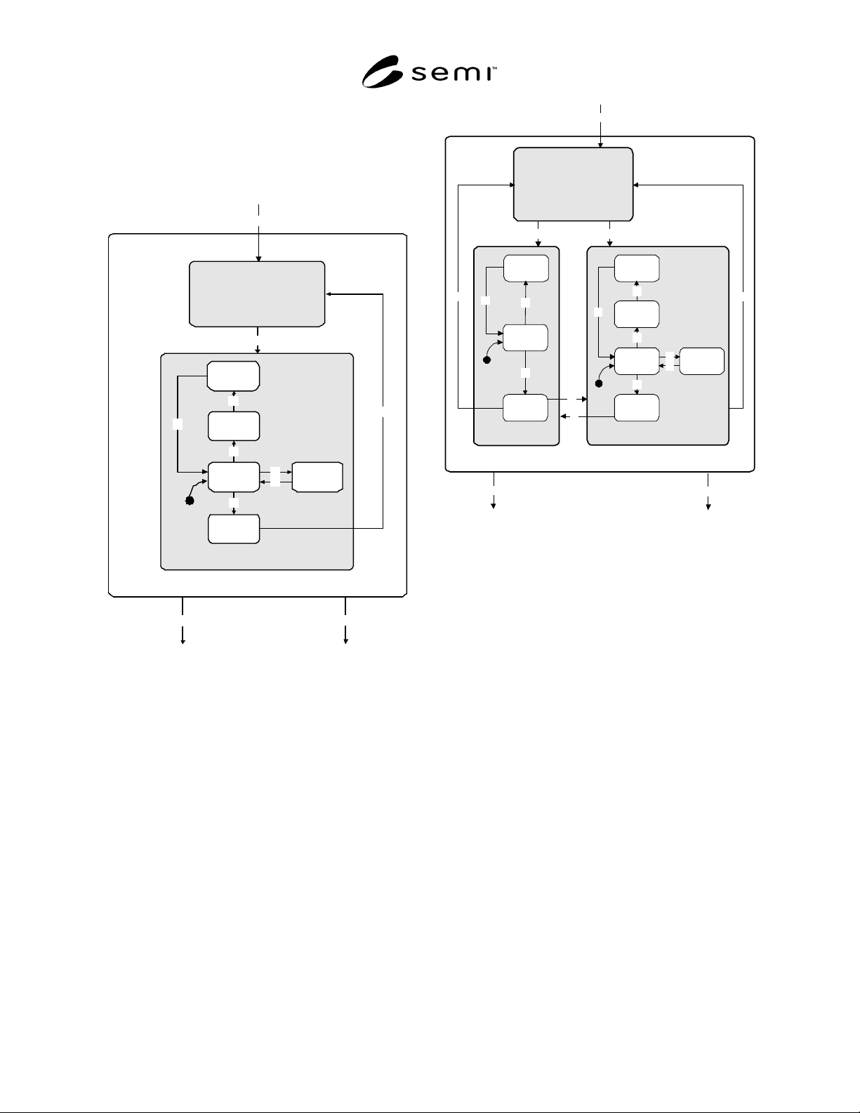
7.2.1 Working State for Inspection Equipment Model
— The processing state model for inspection equipment
is identical to the Generic ISEM Processing State
Model (Figure 1). Only the WORKING state is unique
to the inspection equipment processing state model.
This is shown in Figure 2.
23
24
WORKING
ALIGN
27
INSPECT
INSPECT
REGI ON
INSPECT
SETUP
INSPECT
COMPLETE
29
28
30
31
26
Figure 2
Working State for Inspection Equipment
SEMI 30.1-0200 © SEMI 1998, 20007
7.2.2 Working State for Review Equipment — The
processing state model for review equipment is
identical to the generic ISEM Processing State Model
(Figure 1). Only the WORKING state is unique to the
review equipment processing state model. This is
shown in Figure 3.
23
24
WORKING
A
LIGN
32
REVIEW
CL
A
SSIF
Y
REVIEW
SETUP
REVIEW
COMPLETE
37
35
38
A
CQUIRE
A
NOM
A
L
Y
IM
A
GE
36
A
CQUIRE
A
NOM
A
L
Y
D
A
T
A
34
33
39
26
Figure 3
Working State for Review Equipment
7.2.3 Working State for Inspection/Review Equipment
— The processing state model for inspection/review
equipment is identical to the generic ISEM Processing
State Model (Figure 1). Only the WORKING state is
unique to the inspection/review equipment processing
state model. This is shown in Figure 4.
23
24
WORKING
ALIGN
32
39
REVIEW
CLASSIFY
REVIEW
SETUP
REVIEW
COMPLETE
37
35
38
ACQUIRE
ANOMALY
IMAGE
36
ACQUIRE
ANOMALY
DATA
34
33
27
INSPECT
INSPECT
REGION
INSPECT
SETUP
INSPECT
COMPLETE
29
30
40
41
28
31
26
Figure 4
Working State for Inspection and Review
Equipment
7.3 Processing State Definitions
7.3.1 ABORTED — All activity is suspended as a
result of an ABORT command. Any alarm and abort
conditions shall be cleared before exit from this state.
The CLEANUP command is available to the operator
or host to transition the equipment from the ABORTED
state to IDLE state.
7.3.2 ABORTING (PROCESSING ACTIVE Sub-State)
— The equipment has received an ABORT command.
All normal activity is suspended. The equipment is
taking appropriate action to put the equipment and
material in a “safe state” where possible. Data may be
invalid or not available.
7.3.3 ACQUIRE ANOMALY DATA (REVIEW Sub-
State) — Data is being acquired about anomaly
locations.
7.3.4 ACQUIRE ANOMALY IMAGE (REVIEW Sub-
State) — The equipment is obtaining a view of the
anomaly.
7.3.5 ALARM PAUSED (PAUSE Sub-State) — An
alarm has occurred in the PROCESS or PROCESS
PAUSE states, and the equipment is waiting for the
alarm to be cleared or a command (STOP or ABORT).