semi合集-English.pdf - 第5471页
SEMI P1-1101 © SE MI 1981, 2001 3 14 Packing and Marking 14.1 Substrates shall be packed in a clas s 100 env ironment as defined by ISO 14644-1. Contain ers shall be design ed to prevent g la ss-to-glass contact, and to …
SEMI P1-1101 © SEMI 1981, 2001 2
appropriate to the nominal thickness listed in Table 2.
Dimensions are illustrated in Figures 3 and 4.
7 Material Specifications
7.1 Substrate materials shall be specified as high
thermal expansion (HTE), medium thermal expansion
(MTE), low thermal expansion (LTE), ultra low
thermal expansion (ULTE), durable fused silica (DFS),
or modified fused silica (MFS). Examples of HTE
materials are white crown and soda lime glasses, of
MTE materials are borosilicate and aluminosilicate
glasses, of LTE materials are aluminosiliate glasses,
and of ULTE, DFS, and MFS materials are quartz
(silica).
7.2 Substrate materials shall conform to thermal
expansion and optical transmittance characteristics
specified in Table 3.
7.2.1 DFS shall maintain the transmittance given in
Table 3 within 0.3% change at least accumulated
dosage of 100 kJ/cm
2
of 193 nm wavelength irradiation.
7.3 Selected physical properties of HTE, MTE, LTE,
ULTE, DFS, and MFS materials are provided for
information only in Appendix 1.
8 Flatness Specifications
8.1 Substrates shall be supplied with one side having a
flatness (TIR) of 0.25, 0.5, 1, 2, 5, 10, or 20 µm over a
circular or square quality flatness area as defined in
Figures 5 and 6.
9 Visual Criteria
9.1 A visual quality area, which may or may not
correspond with the flatness area, shall be agreed upon
between the user and supplier.
9.2 Each plate shall not have more defects than listed
in Table 4. This table includes limits for the following
types of defects:
9.2.1 Internal defects in the quality area,
9.2.2 Frontside surface defects,
9.2.3 Backside surface defects, and
9.2.4 Defects outside the quality area.
9.3 Glass substrates shall be identified with notches on
the backside corner as shown in Figure 7. Soda lime
and white crown (HTE) glasses are marked with one
corner notch (Figure 7a). Borosilica and Alumino-
silicate (MTE) glasses are marked with three corner
notches (Figure 7b). Aluminosilica (LTE) glass is
marked with two adjacent corner notches (Figure 7c).
Quartz (ULTE) is marked with two diagonal corner
notches (Figure 7d). Quartz (DFS) is marked with one
corner notch (Figure 7e), that is the same as specified
for HTE. Quartz (MFS) is marked with one non-
isosceles triangle
corner notch (Figure 7f). Dimensions
of notches shall be as specified in Figure 8. If desired,
and so specified in the contract or order, notches are
positioned to identify the squareness origin corner.
10 Sampling
10.1 Unless otherwise specified, appropriate sample
sizes shall be selected from each lot in accordance with
ANSI/ASQC Z1.4. Each quality characteristic shall be
assigned an acceptable quality level (AQL) in
accordance with ANSI/ASQC Z1.4 definitions for
critical, major, and minor classifications. If desired, and
so specified in the contract or order, each of these
classifications may alternatively be assigned cumulative
AQL values. Inspection levels shall be agreed upon
between user and supplier.
11 Test Methods
11.1 Thermal Expansion — Determine in accordance
with ASTM E 228.
11.2 Transmission (to be agreed upon between user
and supplier).
11.3 Irradiation durability (to be agreed upon between
user and supplier).
11.4 Flatness (to be agreed up between user and
supplier).
11.5 Visual (to be agreed upon between user and
supplier).
12 Handling
12.1 Substrates are to be handled on the edges only.
Substrates are to be handled with gloves approved for
cleanroom use.
13 Certification
13.1 Upon request of the purchaser in the contract or
order, a manufacturer's or supplier's certification that
the material was manufactured and tested in accordance
with this specification, together with a report of the test
results, shall be furnished at the time of shipment.
SEMI P1-1101 © SEMI 1981, 20013
14 Packing and Marking
14.1 Substrates shall be packed in a class 100 environment as defined by ISO 14644-1. Containers shall be designed
to prevent glass-to-glass contact, and to protect the substrates from contamination in handling and transit. Substrates
shall be shipped with the acceptable flatness side toward the front of the box. This orientation shall be indicated on
each container. Packaging shall comply with the applicable internal, national, state, and local laws and regulations
required for shipping.
14.2 Containers shall be labeled “Warning: Open and Handle Under Cleanroom Conditions Only”: as well as
identified by user purchase order number (if applicable), drawing number (if applicable), quantity, supplier lot
number, and material identification.
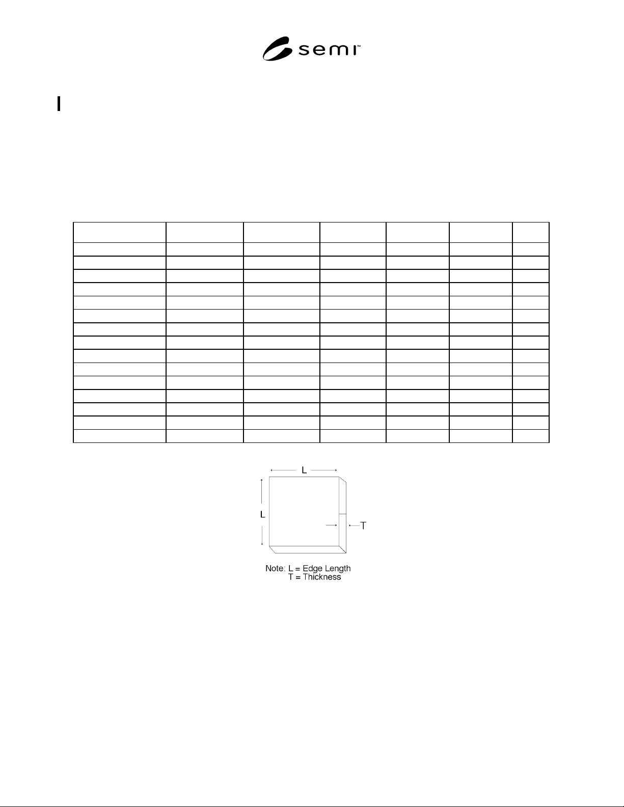
Table 1 Specifications for Edge Length, Squareness, and Thickness for Square Substrates
Nominal Edge Length Edge Length Min. Edge Length Max. Squareness Thickness Min. Thickness Max. Units
2 1/2" Sq. 62.7 63.50 0.05/25.40 1.40 1.60 mm
3" Sq. 75.4 76.2 0.05/25.40 1.40 1.60 mm
3 1/2" Sq. 88.1 88.9 0.05/25.40 1.40 1.60 mm
4" Sq. 100.80 101.6 0.05/25.40 1.40 1.60 mm
2.20 2.40 mm
5" Sq. 126.2 127.0 0.05/25.40 2.20 2.40 mm
3.70 3.90 mm
6.25 6.45 mm
6" Sq. 151.6 152.4 0.05/25.40 2.20 2.40 mm
2.95 3.15 mm
3.70 3.90 mm
6.25 6.45 mm
7" Sq. 177.0 177.8 0.05/25.40 2.95 3.15 mm
3.70 3.90 mm
6.25 6.45 mm
NOTE: HTE squareness is 0.08/25.40
Figure 1
Square Hard Surface Photomask Substrate
SEMI P1-1101 © SEMI 1981, 2001 4
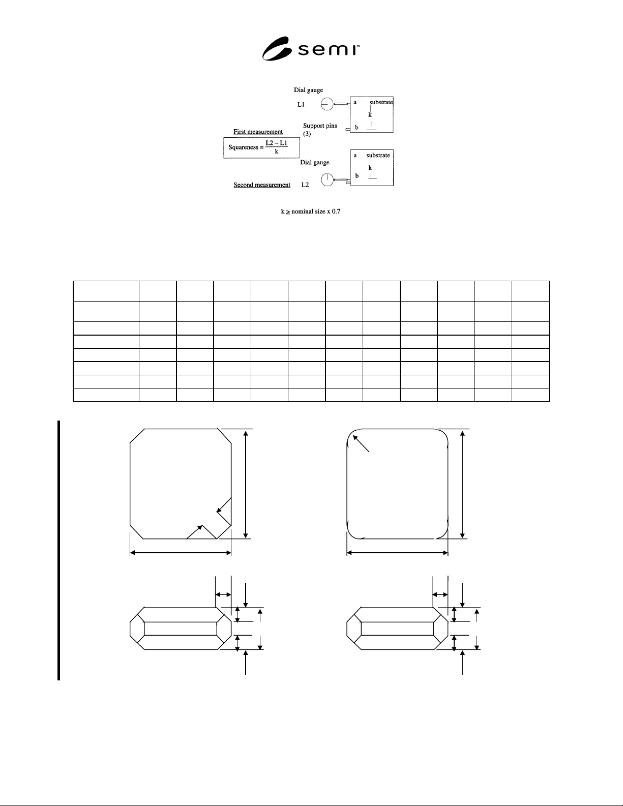
Figure 2
Measurements to Determine Substrate Squareness
Table 2 Specifications for Chamfered and Rounded Edge Dimensions
TAABBCCDDEE
Nominal Min. Max. Min. Max. Min. Max. Min. Max. Min. Max. Units
1.50 0.20 0.50 0.20 0.50 0.30 0.70 2.00 3.00 0.25 0.60 mm
2.30 0.20 0.60 0.20 0.60 0.30 0.70 2.00 3.00 0.25 0.60 mm
3.05 0.20 0.60 0.20 0.60 0.30 0.70 2.00 3.00 0.25 0.60 mm
3.80 0.20 0.60 0.20 0.60 0.30 0.70 2.00 3.00 0.25 0.60 mm
4.57 0.20 0.60 0.20 0.60 0.30 0.70 2.00 3.00 0.25 0.60 mm
6.35 0.20 0.60 0.20 0.60 0.30 0.70 2.00 3.00 0.25 0.60 mm
C
Ed
g
e Len
g
th
Edge Length
A
B
B
T
Ed
g
e Len
g
th
A
B
B
T
D Typ. 4 corners
Edge Length
Figure 3
Chamfered Edge Dimensions