semi合集-English.pdf - 第5128页
SEMI M29-1296 © SEMI 1996, 2003 8 Figure 11 Gasket Area 5.4.4 Clam ping Inde nt — Figure 12 and Table 3 sh ow dimensions of a c oncave part for receiving a clamp. 5.4.4.1 Refer to Fi gure 13 and Table 3 for hori zontal p…
SEMI M29-1296 © SEMI 1996, 2003 7
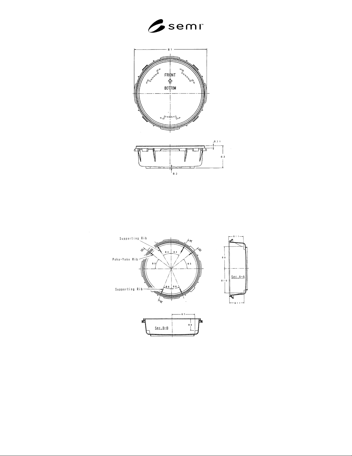
Figure 9
Outer Dimensions of Box Bottom
5.4.2 Supporting Rib and Poka-yoke Rib — Positions of a supporting rib for supporting a shipping cassette inside a
box bottom and a poka-yoke rib provided for avoiding setting the cassette in a wrong orientation are shown in
Figure 10 and Table 3.
Figure 10
Supporting Rib and Poka-yoke Rib
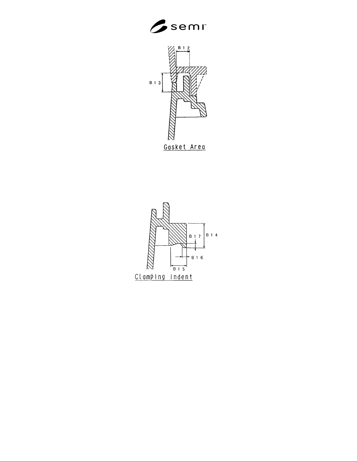
5.4.3 Gasket Area — It is required to provide a gasket in an area shown in Figure 6 and Table 2 if the gasket is
provided.
SEMI M29-1296 © SEMI 1996, 2003 8
Figure 11
Gasket Area
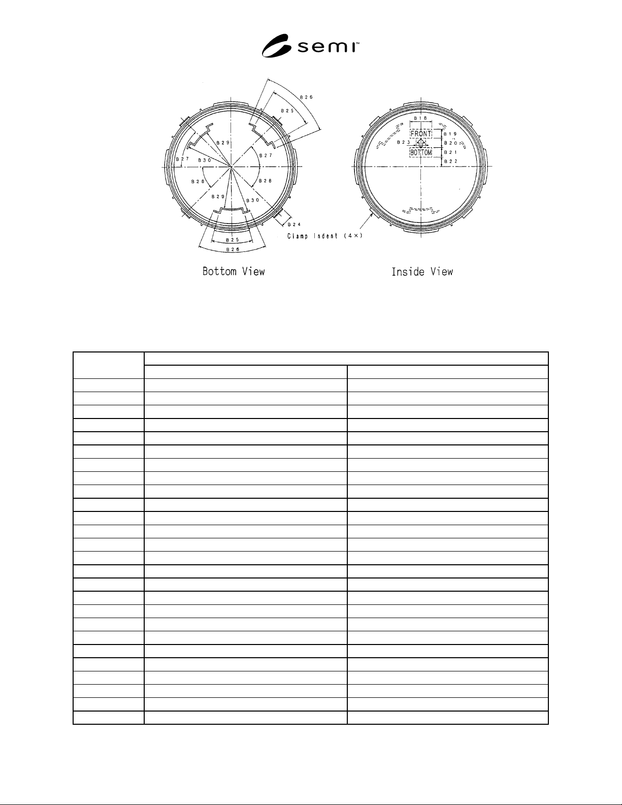
5.4.4 Clamping Indent — Figure 12 and Table 3 show dimensions of a concave part for receiving a clamp.
5.4.4.1 Refer to Figure 13 and Table 3 for horizontal positions.
Figure 12
Clamping Indent
5.4.5 Bottom Rib and Orientation Mark — The position of a bottom rib and the position of an orientation mark are
shown in Figure 13 and Table 3. In addition, since this rib makes a pair with a top rib, this avoids slipping of stacked
shipping boxes, and becomes a datum for positioning the box bottom to equipment.
SEMI M29-1296 © SEMI 1996, 2003 9
Figure 13
Bottom Rib and Orientation Mark
Table 3 Dimensions of Box Bottom
Unit: mm
Standardized Dimension
Location
13 Wafers 25 Wafers
B1 ø 430 max ø 450 max
B2 126.5 ± 1 186.5 ± 1
B3 7 min ←
B4 30° ←
B5 38.5° ←
B6 22.5° ←
B7 158 ± 1 ←
B8 86 ± 1 146 ± 1
B9 156.5 ± 0.5 ←
B10 171.5 ± 0.5 ←
B11 101.5 ± 0.5 161.5 ± 1
B12 10 max ←
B13 18 max ←
B14 16.5 ± 0.5 ←
B15 12 max ←
B16 3 ± 0.5 ←
B17 3 ± 0.5 ←
B18 70 ± 10 ←
B19 30 ± 10 ←
B20 90 ± 10 ←
B21 30 ± 10 ←
B22 30 ± 10 ←
B23 55 ± 10 ←
B24 40 ± 1 ←
B25 27° ←
B26 45° min ←