semi合集-English.pdf - 第3098页
SEMI E125-0305 © SEMI 2003, 2005 6 7.1.3 Equipment m e tadata is desi gned to be useful to applications t hat provide an int erface to hum an end users for the purposes of unde rstanding and browsi ng equipment conf igur…
SEMI E125-0305 © SEMI 2003, 2005 5
Table 2 Association Table Format
Association Role Name Definition Comments
6.1.4.1 Association Role Name — The name of the association role being specified.
6.1.4.2 Definition — Describes the function or purpose of the association.
6.1.4.3 Comments — Any additional comments or notes regarding the association.
6.1.5 Operation Definition Tables — The table below provides an example of the tables used to list and describe the
interface operations defined in this specification.
Table 3 Operation Definition
Operation Description Type
See list below
6.1.5.1 Operation — Specifies the name of the operation.
6.1.5.2 Type — Specifies the messaging semantics of the operation. Only Request-Reply (RR) semantics are used
in this specification. Request-Reply messages are messages that involve an initiator and a receiver. In a Request-
Reply exchange, the initiator sends a single request message to the receiver, and the receiver sends a single reply
message to that request back to the initiator. Fire-and-Forget messages are messages that involve a sender and a
receiver. In a Fire-and-Forget exchange, the sender sends a single message to the receiver, with no associated
response.
6.1.6 Operation Argument Definition Table — The table below provides an example of the tables used to list and
describe arguments for interface operations defined in this specification.
Table 4 Operation Argument Definitions
Argument Description Kind Form
See list below See list below
6.1.6.1 Argument — Specifies the name of the argument.
6.1.6.2 Kind — Specifies whether the argument is an ‘in’, ‘out’, or ‘error’ argument for the operation. ‘Error’
arguments always function as ‘out’ arguments, but indicate that the operation did not complete successfully.
6.1.6.3 Form — Defines the data type of the argument. The terms used to describe data types in this column are
defined in the SEMI Compilation of Terms, or are included as part of the specification. Refer to the compilation of
terms for the definition of SEMI type name meanings.
6.2 Terms
6.2.1 Class, type — This specification uses the terms “class” and “type”, interchangeably to refer to a UML class.
7 Background
7.1 Motivation
7.1.1 This specification is designed to help address the problem of integrating semiconductor equipment from a
variety of suppliers into an automated factory environment, and to provide a standard mechanism for describing
information and data that the equipment can provide for a wide variety of uses. See Related Information 1 for an
overview of some example use cases.
7.1.2 This specification defines the information that is needed to communicate essential features of the equipment
to software applications, and provides extensibility features to allow suppliers to communicate information unique to
their equipment or that may not be specified in a SEMI standard.
SEMI E125-0305 © SEMI 2003, 2005 6
7.1.3 Equipment metadata is designed to be useful to applications that provide an interface to human end users for
the purposes of understanding and browsing equipment configuration, available data items, events, exceptions, etc.
In many cases, these users will be referring to equipment metadata so they can perform data collection for a variety
of objectives (diagnostics, troubleshooting, process control, etc.).
7.1.4 Equipment metadata is also designed to be useful to applications written to take advantage of standardized
state models and other data so that discovery and usage of this information can be automated, without requiring
human intervention. Diagnostics, health monitoring, or other supplier-provided applications that understand the
details of specific equipment types, for example, can also discover and use common equipment-specific
configuration and data without requiring manual assistance.
8 Overview
8.1 Equipment Metadata Organization
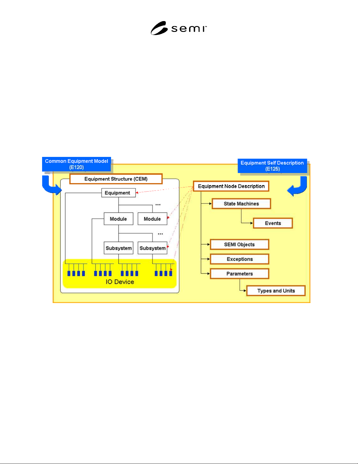
8.1.1 Figure 2 shows the concepts that are included in this specification and their relationship to the SEMI E120
Common Equipment Model. A brief description of the purpose of each metadata concept is provided in this section
only as an overview. For the detailed specification of the corresponding classes, refer to Section 10.
Figure 2
Organization of Metadata Concept
8.1.2 Equipment Node Description
8.1.2.1 This specification defines classes that provide a way to associate events, exceptions, parameters, and SEMI
E39 ObjTypes with any node in the physical equipment structure. SEMI E120 defines the classes that are used to
describe the physical equipment structure; this specification defines the classes that link E120 equipment nodes with
the events, exceptions, parameters, and ObjTypes that they produce. Equipment node description classes are defined
in Section 10.3 .
8.1.3 Parameters
8.1.3.1 This specification defines classes that can be used to describe any variables that are provided by the
equipment, and refers to all such variables as “Parameters”. Parameters can be used to model any concept that can
be represented as a data type. For example, the SEMI E30 concepts of equipment constants, data variables, and
status variables can all be represented by a parameter. Any type of data that the equipment can produce (for
example, measurement results on metrology equipment) can be represented by a Parameter. Parameters can only be

SEMI E125-0305 © SEMI 2003, 2005 7
defined by an equipment node, an SEMI E39 ObjType, or an exception. Parameter description is defined in Section
10.4 .
8.1.4 Type and Units
8.1.4.1 This specification provides a way to describe the data types and units used on the equipment to represent
Parameters. For example, if the equipment defines several Parameters that have a structured data type consisting of
an integer, a string, and an array of Booleans, this specification provides classes that can be used to describe the
structure of that data type. For numeric data types, this specification defines classes that can be used to describe the
units that a value of that data type has. For example, if some Parameter represents a capacitance in microfarads, this
specification can be used to describe the microfarad unit itself, as well as how to indicate that the parameter’s value
is in units of microfarads. Parameter type description is defined in Section 10.4.11 , and units description is defined
in Section 10.5.5 .
8.1.5 State Machine and Events
8.1.5.1 This specification defines classes that can be used to describe the state machines (and the corresponding
transitions and events) that are implemented by the equipment. These classes can be used to describe any SEMI-
defined state machine or any supplier-defined state machine. This specification also defines classes that can be used
to describe the Parameters that are available for reporting when a specific event occurs. State machine description is
defined in Section 10.8 .
8.1.6 SEMI Objects
8.1.6.1 This specification defines classes that can be used to describe any SEMI E39 ObjTypes that are
implemented by the equipment. SEMI ObjType state machines and events are described using the same classes that
are used to describe state machines. ObjType attributes are described using the same classes that are used to
describe Parameters and types. Description of ObjType services is not supported. SEMI ObjType description is
defined in Section 10.8 .
8.1.7 Exceptions
8.1.7.1 his specification defines classes that can be used to describe the existence of error conditions that the
equipment can detect and report as exceptions. An exception can represent any SEMI standard E30 alarm or
equipment-supplier-defined exception that can be reported to clients. Exception description is defined in Section
10.7 .
8.2 Accessing Equipment Metadata
8.2.1 Equipment metadata is directly associated with each unique equipment installation within a factory. Access to
metadata is provided by a collection of operations available from a specific equipment installation. This interface is
described in Section 9.1 .
9 Interfaces for Managing Equipment Metadata
9.1 Equipment Metadata Manager
9.1.1 Figure 3 shows the interface used to access equipment metadata descriptions.