semi合集-English.pdf - 第4742页
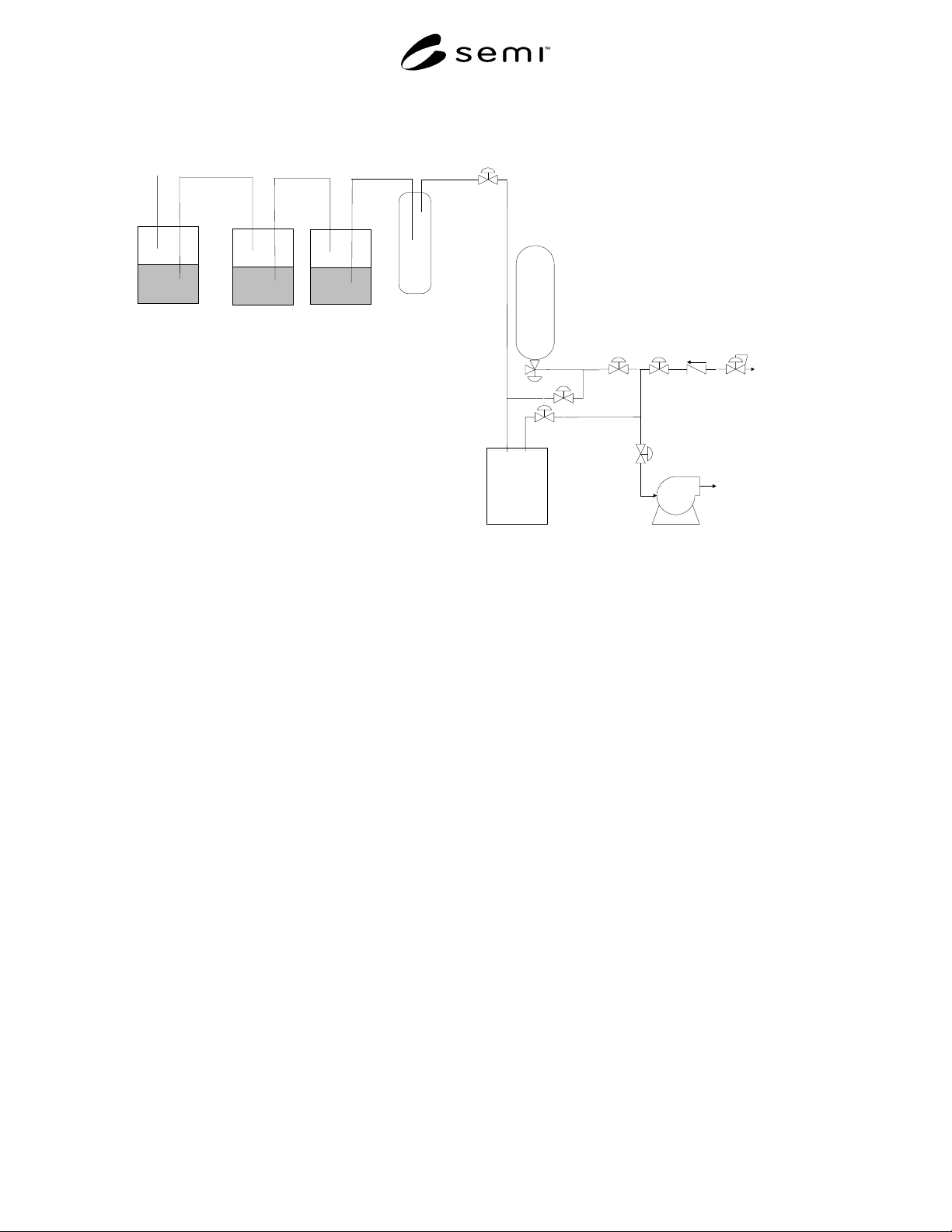
SEMI C3.52-02 00 © SEMI 1995 , 2000 6 V1 V2 V3 V4 V5 V6 Vacuum Pump PFA Vessel House Nitrogen Hydrolysis Vessels Anti Suckback Vessel To Vent Figure 5 Sampling Syste m for WF 6 NOTICE: SEMI m akes no w arranties or repr …
SEMI C3.52-0200 © SEMI 1995, 20005
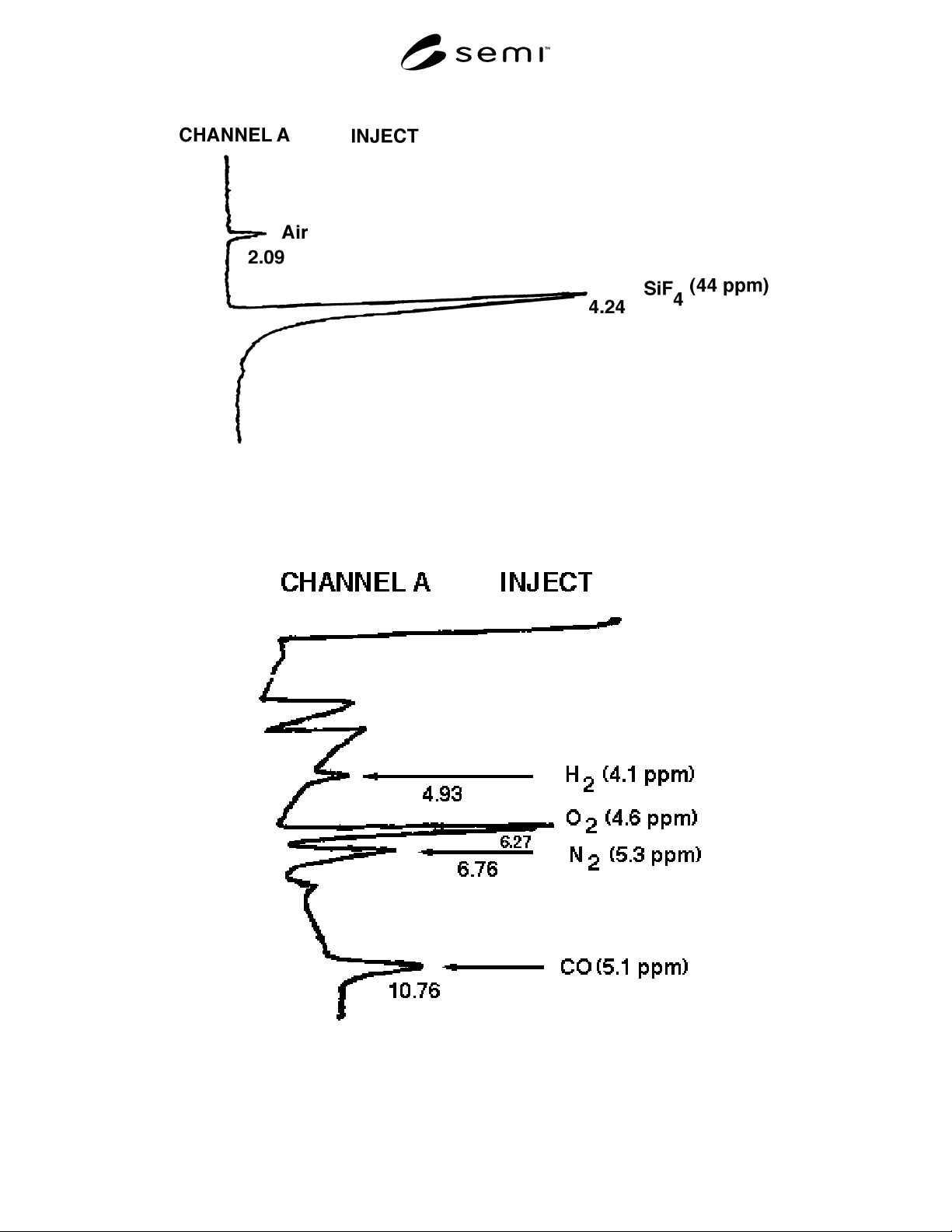
Figure 3
SiF
4
Standard in He
Figure 4
O
2
, N
2
, and CO Standards in He
SEMI C3.52-0200 © SEMI 1995, 2000 6
V1
V2V3
V4
V5
V6
Vacuum Pump
PFA Vessel
House
Nitrogen
Hydrolysis Vessels
Anti Suckback
Vessel
To Vent
Figure 5
Sampling System for WF
6
NOTICE: SEMI makes no warranties or representations as to the suitability of the standards set forth herein for any
particular application. The determination of the suitability of the standard is solely the responsibility of the user.
Users are cautioned to refer to manufacturer’s instructions, product labels, product data sheets, and other relevant
literature respecting any materials mentioned herein. These standards are subject to change without notice.
The user’s attention is called to the possibility that compliance with this standard may require use of copyrighted
material or of an invention covered by patent rights. By publication of this standard, SEMI takes no position
respecting the validity of any patent rights or copyrights asserted in connection with any item mentioned in this
standard. Users of this standard are expressly advised that determination of any such patent rights or copyrights, and
the risk of infringement of such rights, are entirely their own responsibility.
Copyright by SEMI® (Semiconductor Equipment and Materials
International), 3081 Zanker Road, San Jose, CA 95134. Reproduction o
f
the contents in whole or in part is forbidden without express written
consent of SEMI.
SEMI C6.3-89 © SEMI 1989, 2003 1
SEMI C6.3-89 (Reapproved 0303)
PARTICLE SPECIFICATION FOR GRADE 20/0.2 HYDROGEN (H
2
)
DELIVERED AS PIPELINE GAS
This specification was technically approved by the Global Gases Committee and is the direct responsibility of
the North American Gases Committee. Current edition approved by the North American Regional Standards
Committee on October 25, 2002. Initially available at www.semi.org December 2002; to be published March
2003. Originally published in 1989.
1 Purpose
1.1 The purposes of this document are (1) to set a
maximum permissible particle concentration for Grade
20/0.2 hydrogen gas and (2) to describe a reference
method for its verification.
2 Scope
2.1 This document applies only to hydrogen gas
delivered through pipelines; it is not applicable to
cylinder gases or gases in their liquid state.
NOTICE: This standard does not purport to address
safety issues, if any, associated with its use. It is the
responsibility of the users of this standard to establish
appropriate safety and health practices and determine
the applicability of regulatory or other limitations prior
to use.
3 Referenced Standards
None.
4 Terminology
4.1 Definitions
4.1.1 background count — The total number of counts
registered by a specific particle counter within the time
needed to sample 1.0 SCF of gas under conditions
where zero particles transverse the sensing volume,
averaged over at least a sequence of twenty-four
consecutive sampling periods of 1.0 SCF each or eight
consecutive periods of 30 minutes each, whichever is
longer. The background count is to be reported as
mean number of count per SCF; the number of hours on
which the average is based is also reported.
4.1.2 gas sample volume — The volume of the sample,
expressed in standard cubic feet (SCF) is the volume
occupied by the gas sample at standard conditions,
20° C (68° F) and 1.00 atmosphere pressure.
4.1.3 particle concentration — The total number of
particles counted, divided by the total gas sample
volume, and corrected for background count as defined
in Section 4.1.1, rounded to the nearest integer, for
particles equal to or larger than the specified size.
4.1.4 particle size/particle diameter — The optical
equivalent diameter as detected by a given light
scattering particle counter.
NOTE 1: The optical equivalent diameter varies from counter
to counter and with differing particle shape and refractive
index.
4.1.5 sampling period — The time needed to sample
1.0 SCF or 30 minutes, whichever is longer.
5 Apparatus
5.1 Light Scattering Optical Particle Counter — With
a lower detection limit of 0.2 micrometers or less, based
on a calibration with polystyrene latex spheres; and
with a maximum background of 2 counts/SCF at 0.2
micrometers. It should be suitable for use in hydrogen
service per the manufacturer' s specifications or encased
in an explosion-proof enclosure which satisfies Class I,
Division I of the NFPA Code.
6 Test Method
NOTE 2: The precise details of any sampling configuration,
measurement procedure, or any instrument calibration
procedure and frequency must be agreed upon between user
and supplier, taking into account good engineering practice.
6.1 The sampling point should be as close as practical
to the downstream side of the supplier' s final gas filter.
Sampling lines should be as short as possible.
6.2 Suggested sampling probe configuration for
turbulent main line flow:
Alternative a: Figure 1a (preferred)
Alternative b: Figure 1b
Alternative c: Figure 1c
Alternative d: Figure 1d
6.3 For configurations 1a, 1b, and 1c, the flow rate in
the sampling tube at pipeline pressure should be set so
that the mean sampling flow velocity at the probe inlet
matches as closely as possible the axial flow velocity in
the pipeline. Sampling tube ID should be no less than 2
mm (0.08 in).