semi合集-English.pdf - 第196页
SEMI E24-92 © SEMI 1992, 2004 3 RELATED INFORMATION 1 NOTICE : This relate d informati on is not an offici al part of SEMI E24 but was reapp roved for publication by full letter ballot procedures on Feb ruary 28, 1999. R…

SEMI E24-92 © SEMI 1992, 2004 2
Section 4.3.1. Pins 5 and 6 are connected to the circuit
which enables opening of the module' s isolation valve
at that interface. Pins 7 and 8 are connected across the
contacts of the relay specified in Section 4.3.2. Pins 9
and 10 are connected to the circuit which enables
closure of the module' s isolation valve at that interface.
4.7.2 Cable and Plugs — Pins 2 and 3 of each plug on
the interlock cable are connected to pins 5 and 6
respectively of the other plug. Pins 7 and 8 of each plug
on the interlock cable are connected to pins 9 and 10
respectively of the other plug. The resulting interlock
cable is symmetric.

SEMI E24-92 © SEMI 1992, 2004 3
RELATED INFORMATION 1
NOTICE: This related information is not an official part of SEMI E24 but was reapproved for publication by full
letter ballot procedures on February 28, 1999.
R1-1 Interlock Situations
R1-1.1 Examples are given below, for the different
types of modules, of situations in which it might be
considered hazardous for a connected module to
operate its isolation valve. Note that some of these
conditions prevent opening and others prevent closing
of the valves. (See Section 4.1.). Module types are
defined in SEMI E21. SEMI S2 provides guidance in
defining potential safety hazards. It is common practice
to detect valve positions and so verify operation, but
this is not an interface matter.
R1-1.2 Transport Module Examples — The transport
module end effector (see SEMI E22) is extended
beyond the interface plane. The connected module
should not close its isolation valve, as such an operation
could damage the end effector.
R1-1.2.1 The transport module is not at an acceptable
transfer pressure. Opening the isolation valve of the
connected module could result in damage to the valve
or wafer.
R1-1.3 Process Module Examples — The transport
module end effector exclusion volume (see SEMI E22)
is obstructed. The transport module should not open its
isolation valve and attempt to extend its end effector.
R1-1.3.1 The process module is not at an acceptable
transfer pressure. For instance, the module may be at
atmospheric pressure for preventive maintenance. The
transport module should not open its isolation valve.
R1-1.3.2 An unsafe partial pressure of a hazardous gas
exists in the process module. The transport module
should not attempt to open its isolation valve.
R1-1.4 Cassette Module Example — The cassette port
(loading door) is open, indicating the possibility of a
person' s hand in the cassette module. The transport
module should not operate its isolation valve to avoid
the possibility of injury to personnel.
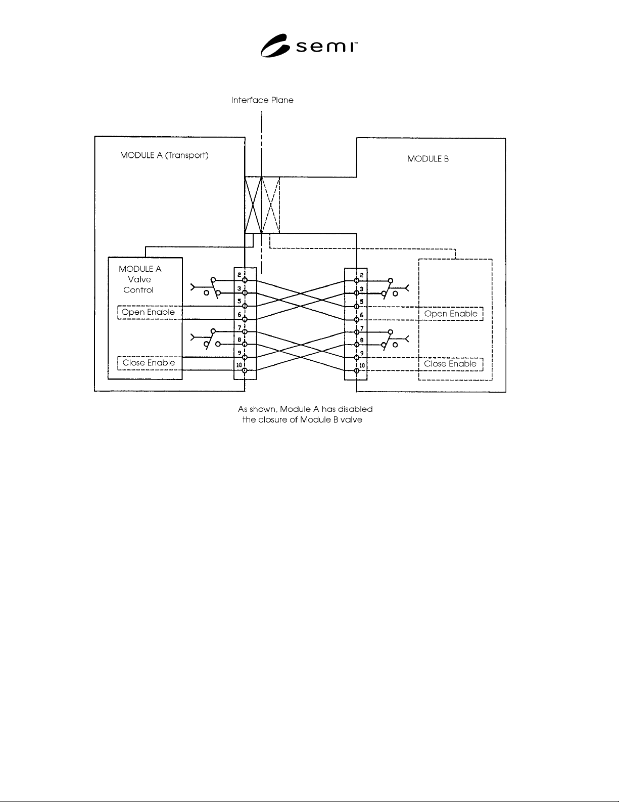
R1-2 Illustration of Logic
R1-2.1 The interlock logic is illustrated in Figure A1
and described in Section 4.2. In the figure, the contacts
in module B are closed, enabling operation of the
isolation valve controlled by module A, while one of
the contacts in module A is open, preventing closure of
the isolation valve controlled by module B.
R1-3 Interlock Example
R1-3.1 This example elucidates some of the interlock
logic described in Section 4.2. In the case described
here, the Transport Module (TM) end effector is
extended into a Process Module (PM), which is
equipped with an isolation valve. This valve is inhibited
from closing by the interlock in the TM.
R1-3.2 A situation arises in the PM which results in its
interlock inhibiting the opening of the isolation valve
(which is already open) on the TM. As specified in
Section 4.3.3, the TM detects the interlock change and
immediately withdraws its end effector from the PM.
The TM interlock enables the closure of the PM
isolation valve (which the PM may do if that is the
appropriate response to the situation) and the TM can
close its isolation valve.
SEMI E24-92 © SEMI 1992, 2004 4
Figure R1-1
Illustration of Isolation Valve Interlock Standard
NOTICE: The user’s attention is called to the
possibility that compliance with this standard may
require use of an invention covered by patent rights. By
publication of this standard, Semiconductor Equipment
and Materials International (SEMI) takes no position
respecting the validity of any patent rights asserted in
connection with any item mentioned in this standard. In
particular, users of the specification should be aware
that Drytek, Inc., A Unit of General Signal, 16 Jonspin
Road, Wilmington, MA 01887-1087, Phone: (508) 657-
3933, has neither claimed nor disclaimed that
compliance with this specification would require use of
an invention covered by one or more of its patents.
Users of this standard are expressly advised that
determination of any such patent rights, and the risk of
the infringement of such rights, are entirely their own
responsibility.
These standards do not purport to address safety issues,
if any, associated with their use. It is the responsibility
of the user of these standards to establish appropriate
safety and health practices and determine the
applicability of regulatory limitations prior to use.
SEMI makes no warranties or representations as to the
suitability of the standards set forth herein for any
particular application. The determination of the
suitability of the standard is solely the responsibility of
the user. Users are cautioned to refer to manufacturer’s
instructions, product labels, product data sheets, and
other relevant literature respecting any materials
mentioned herein. These standards are subject to
change without notice.
Copyright by SEMI® (Semiconductor Equipment and Materials
International), 3081 Zanker Road, San Jose, CA 95134. Reproduction o
f
the contents in whole or in part is forbidden without express written
consent of SEMI.