semi合集-English.pdf - 第184页
SEMI E23-1104 © SEMI 1991, 2004 2 3.2 ISO St andards 1 ISO 4902 — Info rmation Technology — Data Communicat io n — 37-pol e DTE/DCE Inter face Connector and Con tact Number Assignm ents 3.3 Japanese Industrial Standards …
SEMI E23-1104 © SEMI 1991, 2004 1
SEMI E23-1104
SPECIFICATION FOR CASSETTE TRANSFER PARALLEL I/O
INTERFACE
This specification was technically approved by the Global Physical Interfaces and Carriers Committee and is
the direct responsibility of the North American Physical Interfaces and Carriers Committee. Current edition
approved by the North American Regional Standards Committee on August 16, 2004. Initially available at
www.semi.org September 2004; to be published November 2004. Originally published in 1991; previously
published in 2002.
1 Purpose
1.1 Cassette transfer between process equipment and
transport equipment is performed by means of a
mechanical operation in the interactive area and
requires quick response and reliable interlock signals.
1.2 The purpose of this specification is to provide a
cassette transfer parallel input/output (I/O) interface for
control of the interface mechanism that supplements the
SECS standard for material movement.
2 Scope
2.1 This specification deals with the parallel I/O
interface for the cassette transfer between two pieces of
equipment, such as a piece of process equipment and a
piece of transport equipment.
2.2 This standard defines the wire-connected parallel
I/O interface between two pieces of equipment and the
photo-coupled parallel I/O interface between the
process equipment and the transport equipment.
2.3 The application of the parallel I/O interface to the
cassette transport is as follows.
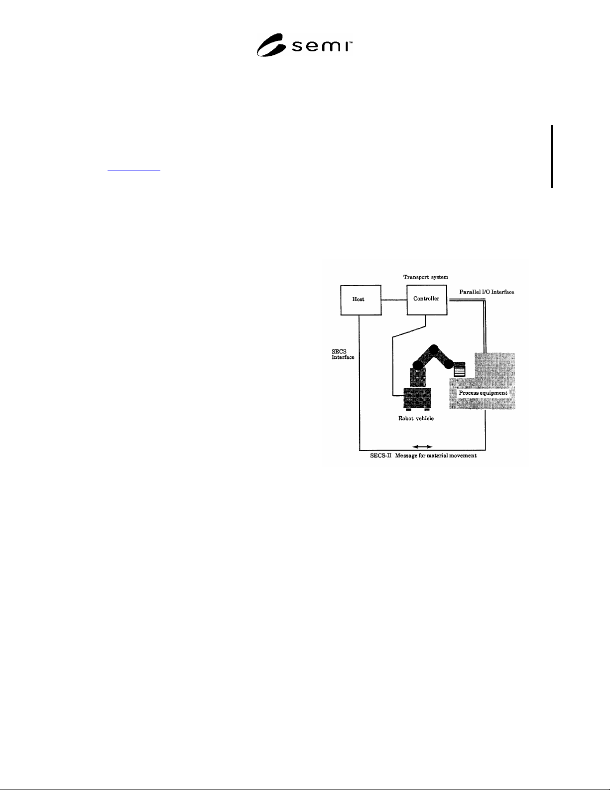
2.4 Each piece of equipment is connected to the HOST
at the SECS interface, and each of the two pieces of
equipment between which the cassette transfer will be
made is connected at the parallel I/O interface as shown
in Figure 1.
2.5 The cassette transfer request, or load/unload
command, is notified by the SECS-II message. The
actual cassette transfer action is executed using the
parallel I/O interface, interlocking each mechanism.
(An example of a cassette transfer transaction using the
parallel I/O interface is shown in Related Information
1.)
NOTICE: This standard does not purport to address
safety issues, if any, associated with its use. It is the
responsibility of the users of this standard to establish
appropriate safety and health practices and determine
the applicability of regulatory or other limitations prior
to use.
Figure 1
Application of Parallel I/O Interface to Cassette
Transport
3 Referenced Standards
3.1 SEMI Standards
SEMI E1 — Specification for 3 inch, 100 mm, 125
mm, and 150 mm Plastic and Metal Wafer Carriers
SEMI E4 — SEMI Equipment Communications
Standard 1 Message Transfer (SECS-I)
SEMI E5 — SEMI Equipment Communications
Standard 2 Message Content (SECS-II)
SEMI E23-1104 © SEMI 1991, 2004 2
3.2 ISO Standards
1
ISO 4902 — Information Technology — Data
Communication — 37-pole DTE/DCE Interface
Connector and Contact Number Assignments
3.3 Japanese Industrial Standards Committees
2
JIS-X-5103 — The Interface Between Data Circuit
Terminating Equipment (DCE) and Data Terminal
Equipment (DTE) (37/9-Pin Interface)
NOTICE: Unless otherwise indicated, all documents
cited shall be the latest published versions.
4 Terminology
4.1 Definitions
4.1.1 active equipment — Equipment that loads a
cassette onto the cassette stage of another piece of
equipment or unloads a cassette from the cassette stage
of another piece of equipment.
4.1.2 cassette — A plastic or metal wafer carrier as
defined in SEMI E1.
4.1.3 cassette stage — A stage on a piece of equipment
on which a cassette is placed or from which it is
removed that allows the cassette transfer.
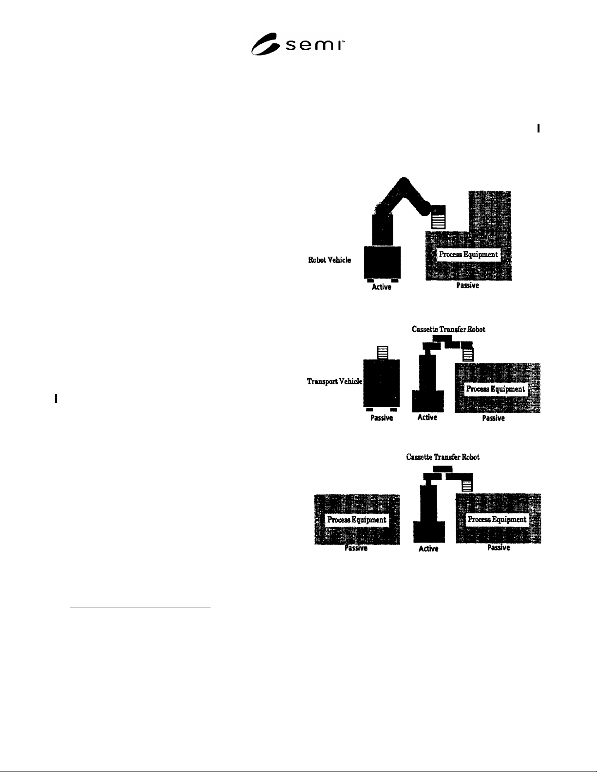
4.1.4 cassette transfer robot — A robot that transfers
cassettes (see Figure 2).
4.1.5 passive equipment — Equipment that is loaded or
unloaded by the active equipment.
4.1.6 photo-coupled interface — A parallel I/O
interface connected without contact by means of a
photo-coupled device.
4.1.7 process equipment — Fabrication equipment,
inspection equipment, and cassette stage equipment
used in semiconductor manufacturing.
4.1.8 robot vehicle — A piece of equipment having a
cassette transfer robot on the vehicle that moves to
another piece of equipment and transfers cassettes (see
Figure 2).
4.1.9 transfer — To either load or unload.
4.1.10 transport equipment — A piece of equipment
(or system) which transports or transfers cassettes. It
1 International Organization for Standardization, ISO Central
Secretariat, 1, rue de Varembé, Case postale 56, CH-1211 Geneva 20,
Switzerland. Telephone: 41.22.749.01.11; Fax: 41.22.733.34.30
Website: www.iso.ch
2 Japanese Industrial Standards, Available through the Japanese
Standards Association, 1-24, Akasaka 4-Chome, Minato-ku, Tokyo
107-8440, Japan. Telephone: 81.3.3583.8005; Fax: 81.3.3586.2014
Website: www.jsa.or.jp
mainly consists of a transport vehicle, a robot vehicle,
and a cassette transfer robot.
4.1.11 transport vehicle (see Figure 2) — A vehicle
which transports cassettes but which has no mechanism
for cassette transfer.
4.1.12 wire-connected interface — A parallel I/O
interface connected by means of wire and a connector.
Figure 2
Cassette Transfer between Active Equipment
and Passive Equipment
SEMI E23-1104 © SEMI 1991, 2004 3
5 Parallel I/O Interface Specification
5.1 This standard refers only to the cassette transfer between active and passive equipment.
5.2 Wire-Connected Parallel I/O Interface Specification — The equipment is to have a parallel I/O interface for the
passive mode when it becomes passive, and the parallel I/O interface for the active mode when it becomes active.
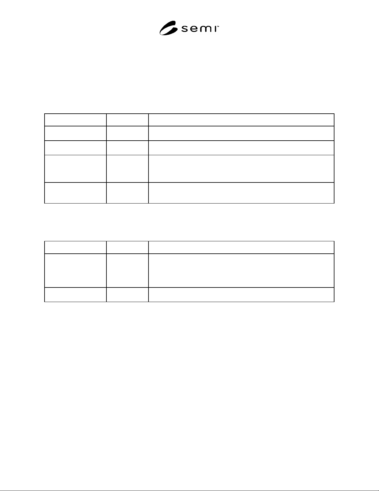
5.2.1 Signals for Each Cassette Stage — The cassette stage is to have the input/output signal lines listed in Table 1.
Table 1 Signals for Each Cassette Stage (Wire-Connected Interface)
Signal Type P/A Description
L_REQ (LOAD
REQUEST)
P->A This signal means that the CS can be loaded. The signal turns OFF when the
cassette is detected on the CS. (The CS is a cassette stage.)
U_REQ (UNLOAD
REQUEST)
P->A This signal means that the CS can be unloaded. The signal turns OFF when it is
detected that the cassette has been removed from the CS.
READY P->A This signal means that the CS is in a state where it can be accessed by the active
equipment. It turns ON when the CS is in the READY state after the TR_REQ
signal from the active turns ON. The signal turns OFF by handshakes with the
COMPT signal.
TR_REQ (TRANSFER
REQUEST)
A->P This signal turns ON when the active equipment is going to start transferring the
cassette. It turns OFF when the BUSY signal is OFF. (Active equipment starts
transferring the cassette with the BUSY ON after recognizing the READY ON.)
5.2.2 Common Signals — The signals in Table 2 show the status of the cassette transfer action of the active
equipment. The CS’s are allowed to input these signals commonly from active equipment.
Table 2 Common Signals (Wire-Connected Interface)
Signal Type P/A Description
BUSY A->P This signal turns ON when the active equipment starts transferring the cassette to
the CS while it is in READY and turns OFF after the robot has loaded or unloaded
a cassette and has moved away from the interactive zone. The passive equipment
does not perform any mechanical action in the interactive zone while this signal is
ON.
COMPT (COMPLETE) A->P This signal means the active equipment has completed the transfer action. It turns
OFF after handshaking with the READY signal.
NOTE 1: It is recommended that the BUSY signal turn OFF after the active equipment has confirmed L_REQ (or U_REQ) is
OFF.
5.2.3 Cassette Transfer Sequence — Time charts for the cassette transfer sequence are shown in Figures 3 (a) and
(b).
5.2.3.1 The TR_REQ from the active equipment initiates the cassette transfer sequence. The active equipment starts
carrying out the transfer action with the BUSY ON as soon as it recognizes that the READY signal of the passive
equipment is ON. The handshake is finished after the cassette transfer action has been completed.
5.3 Photo-Coupled Parallel I/O Interface Specification — This interface is concerned only with the cassette transfer
between the process equipment and the transport robot vehicle. The robot vehicle is active and the process
equipment is passive.
5.3.1 This interface is defined between the robot and the cassette stages to which the robot can transfer a cassette at
the same stopping position.
5.3.2 Signals — The signals for the photo-coupled parallel I/O interface are listed in Table 3. The CS_0, CS_1, and
CS_2 signals specifying the CS to or from which the active equipment transfers and the VALID signal indicating
effectiveness of the data of CS_0~CS_2, are newly added to the signals defined in the wire-connected parallel I/O
interface.